


Serial port configuration task list 56
OnSite 2800 Series User Manual 4 • Serial port configuration
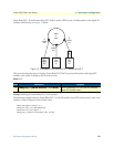
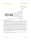
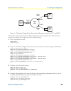
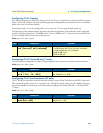
Figure 14. IP Context with logical IP interfaces bound to Ethernet port, serial port PVC 1 and PVC 2
The related IP, serial interface and Frame Relay configuration procedure is listed below. Where necessary,
comments are added to the configuration for better understanding.
1. Enter the configuration mode.
2800>enable
2800#configure
…
2. Set up the IP interface configuration first. Be aware that not all of the necessary settings are listed below.
2800(cfg)#context ip router
2800(ctx-ip)[router]#interface external
2800(if-ip)[external]#interface internal
2800(if-ip)[internal]#interface lan
2800(if-ip)[lan]#exit
2800(ctx-ip)[router]#interface internal
2800(if-ip)[internal]#ipaddress 192.168.3.1 255.255.255.0
2800(if-ip)[internal]#interface external
2800(if-ip)[external]#ipaddress 192.168.2.1 255.255.255.0
2800(if-ip)[external]#interface lan
2800(if-ip)[lan]#ipaddress 192.168.1.1 255.255.255.0
…
3. Configure the serial interface settings.
2800(cfg)#port serial 0 0
2800(prt-ser)[0/0]#shutdown
2800(prt-ser)[0/0]#encapsulation framerelay
…
4. Configure the Frame Relay. You must thus change to the Frame Relay configuration mode. Use the ser-
vice-policy profile defined above to give voice priority over data.
2800(prt-ser)[0/0]#framerelay
2800(frm-rel)[0/0]#lmi-type ansi
2800(frm-rel)[0/0]#keepalive 20
…
Context
IP
“router”
192.168.2.1
IP interface
external
PVC 1
Port
Serial
0 0
192.168.3.1
Port
Ethernet
0 0
IP interface
lan
192.168.1.1
PVC 2
Port
Serial
0 0
IP interface
external