


Serial port configuration task list 49
OnSite 2800 Series User Manual 4 • Serial port configuration
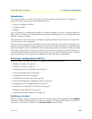
2800(cfg)#port serial 0 0
2800(prt-ser)[0/0]#framerelay
2800(frm-rel)[0/0]#lmi-type ansi
Configuring the keep-alive interval
A keep-alive interval must be set to configure the LMI. By default, this interval is 10 seconds and, according to
the LMI protocol, must be less than the corresponding interval on the switch. The keep-alive interval in sec-
onds, which is represented by number, has to be in the range from 1 to 3600.
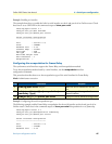
This procedure describes how to set the keep-alive interval
Mode: Frame Relay
To disable keep-alives on networks that do not utilize LMI, use the
no keepalive interface
configuration command.
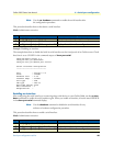
Example: Configuring the keep-alive interval
The following example sets the keepalive interval to 10 seconds for Frame Relay over the serial interface on slot
0 and port 0 of an OnSite router.
2800(cfg)#port serial 0 0
2800(prt-ser)[0/0]#framerelay
2800(frm-rel)[0/0]#keepalive 10
Entering Frame Relay PVC configuration mode
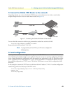
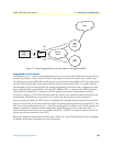
The permanent virtual circuit (PVC) is a virtual circuit that is permanently established. PVCs save bandwidth associ-
ated with circuit establishment and tear down in situations where certain virtual circuits must exist all the time.
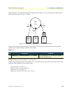
The Frame Relay network provides a number of virtual circuits that form the basis for connections between
stations attached to the same Frame Relay network.
The resulting set of interconnected devices forms a private Frame Relay group, which may be either fully inter-
connected with a complete mesh of virtual circuits, or only partially interconnected.
In either case, each virtual circuit is uniquely identified at each Frame Relay interface by a Data Link Connection
Identifier (DLCI). In most circumstances, DLCIs have strictly local significance at each Frame Relay interface.
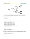
Assigning a DLCI to a specified Frame Relay sub interface on the OnSite is done in the PVC configuration
mode. The DLCI has to be in the range from 1 to 1022.
Note
A maximum of eight PVCs can be defined.
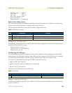
This procedure describes how to enter the PVC configuration.
Step Command Purpose
1 node(frm-rel)[slot/port]#keepalive number Sets the LMI keep-alive interval