Model 2977 B4 ST adapter installation 28
Model 2977 DialFire RAS User Manual 3 • Installing the Model 2977 adapter
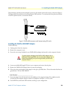
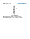
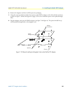
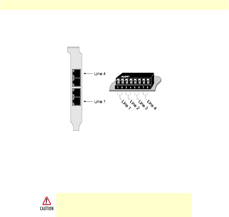
The terminating switches must be changed in pairs (one for transmit and one for receive), as shown in figure 3.
The figure shows the switches set for no termination (OFF position). To terminate the lines, place the switches
in the ON position (down, or toward the board).
Figure 3. DialFire BRI connectors and line-terminating DIP switch
Installing the DialFire RAS B4ST Adapter
Do the following:
1. Unplug power from the computer.
2. Remove the computer’s cover.
3. Put on the wrist strap (included in your DialFire RAS package) and attach it to the computer’s chassis.
4. Locate an available full-length PCI slot in your computer and remove the slot plate.
5. Remove the DialFire RAS adapter from its protective packaging.
6. Write down the serial number of the adapter in the space provided below. The serial number label has the
general form: “S/N (S) XXX XXXXX”
Serial Number: ________________________
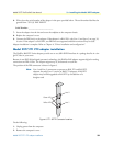
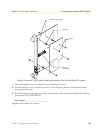
7. Insert the adapter into the slot and screw the endplate to the computer chassis. The endplate must be
screwed into the computer chassis to remain in compliance with Part 15 of FCC rules.
8. Set the BRI line termination DIP switches according to your configuration.
To guard against damage to the DialFire RAS adapter due to
electrostatic discharge (ESD), do not remove the adapter from its
protective packaging until you have grounded yourself to the
computer chassis


