


3040/V35
139001UA
2-2
INSTALLATION AND OPERATIONS MANUAL
SETUP & INSTALLATION
PATTON ELECTRONICS CO.
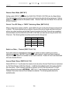
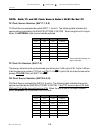
Switch 18 - 1, 2, 3, 7 and 8 to
OFFOFF
OFFOFF
OFF, 4, 5 and 6 to
ONON
ONON
ON
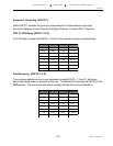
Anti-Stream timer = 2 M bits
Anti-Stream = Disabled
Broadcast Data to Sub-Channels
RX Clock Source = Master
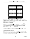
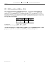
JP4 Thru JP7
OpenOpen
OpenOpen
Open
HS Option Not Enabled
JP8 thru JP12 to
OpenOpen
OpenOpen
Open
DTR / DSR Not Forced
JP1 Thru JP3 to
InstalledInstalled
InstalledInstalled
Installed
Factory Test Jumpers
If the system application requires one or more of the default settings to be changed, it will be
necessary to remove the top cover of the enclosure to access and change the DIP switches
located on the printed circuit board.
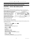
Disassembly
Remove the top cover by removing the phillips head screws located on the left and right sides
of the 3040/V35 (CTS MD-V.35/TCB). DTE/DCE switches SW5 through SW14, baud rate
Jumpers JP4 through JP7, interface Jumpers JP8 through JP12 and configuration switches
SW15 through SW18 are located on the PCB as indicated on the strapping guide in the
Appendix of this manual. After the switch selection activity is completed,
re-install the top
cover BEFORE connecting to a AC power source
.
Installation
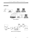
Select an appropriate location accessible to and within six feet of an AC power outlet, the
outlet must have a ground pin receptacle for product warranty. The DCE-to-DTE cabling
between each attached device and the 3040/V35 (CTS MD-V.35/TCB) should be “Straight
Through”, shielded and terminated with male connectors. Sub-Channels are marked PORT 1
through PORT 4, the Master Port is marked, MASTER DCE/DTE. If any terminal has a priority
service mode, ensure it is connected to the port connector designated “PORT 1” on the rear
panel of the 3040/V35 (CTS MD-V.35/TCB). Secure other terminals or Modems to be
serviced to the remaining “PORT” connectors. Connect the MODEM or TERMINAL to the
connector designated “MASTER DTE/DCE”.