


3040/V35
139001UA
2-1
INSTALLATION AND OPERATIONS MANUAL
SETUP & INSTALLATION
PATTON ELECTRONICS CO.
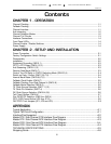
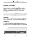
Caution, Disconnect the POWER Before Removing The Cover
Vorsicht, Befor Deckung Abnehmen Mach Strom Zu.
CHAPTER 2 - SETUP AND INSTALLATION
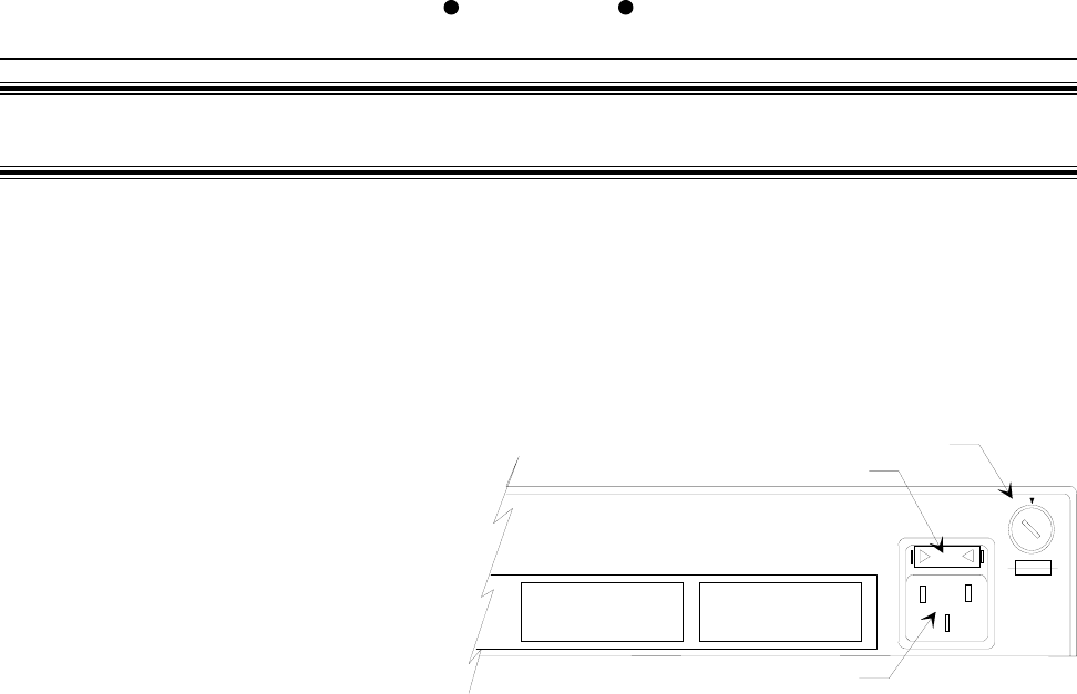
Power Connection
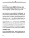
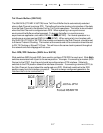
Before connecting the 3040/V35 (CTS MD-V.35/TCB) to a AC power source the top cover
must be installed and secured with the supplied #8-32 screws. The unit is supplied with a 110/
220VAC voltage switch, turn the switch with
a coin or screw driver to the appropriate
voltage for your country. EXAMPLE: In
the United States of America; set to
110VAC. The unit is supplied with a
IEC power connector next to the
voltage select switch, plug the power
cord into the connector until it is firmly
seated. You may now connect the
power cord into your AC outlet.
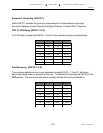
Factory Configuration Switch Settings
The 3040/V35 (CTS MD-V.35/TCB) is configured prior to shipment with the switches set to the
following default positions:
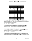
Switch 15 - 1,2,3, 4 and 8 to
OFFOFF
OFFOFF
OFF, 5, 6 and 7 to
ONON
ONON
ON.
No Data Time Out = 2048 bits
Internal Baud Rate = 56000
Chassis Ground not connected to Signal Ground
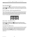
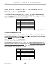
Switch 16 - All to
ONON
ONON
ON.
CTS Delay = No Delay
Sync Mode
Contention Mode = Priority
Fallback Clock = Disabled
Fallback Clock Mode = Data Transitions
Fallback Clock Source = Internal Baud Rate Generator
Switch 17 - All to
ONON
ONON
ON.
TX Clock Source = Master pin 15
Sub-Channel Activity Indicated by Interface Control (RTS/DCD)
WARNING: FOR CONTINUED PROTECTION
AGAINST RISK OF FIRE, REPLACE ONLY
WITH SAME TYPE AND RATING FUSE.
110 / 220VA Switch
Fuse Drawer
PORT 4 MASTER DTE/ DCE
IEC Power Connector
110
220