


3040/V35
139001UA
2-6
INSTALLATION AND OPERATIONS MANUAL
SETUP & INSTALLATION
PATTON ELECTRONICS CO.
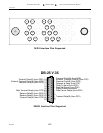
NOTE: Both T X and RX Clock Source Select MUST Be Set !!!!
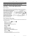
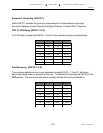
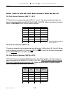
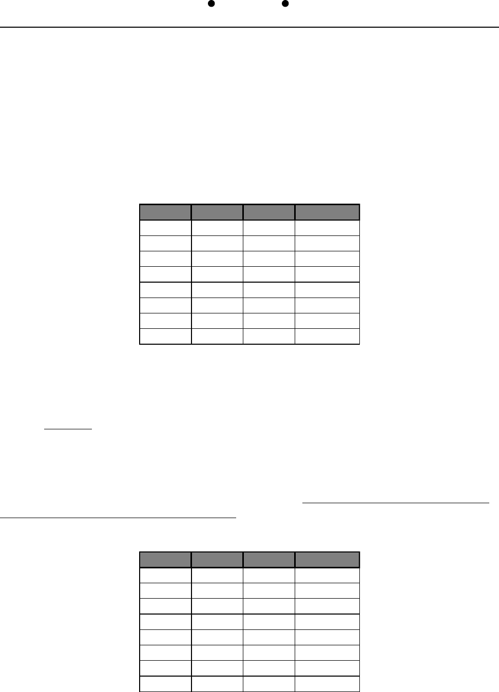
TX Clock Source Selection (SW17-1,2,3)
TX Clock Source is selected by switch SW17-1, 2 and 3. The following table indicates the
source options provided by the 3040/V35 (CTS MD-V.35/TCB). When using the unit in Async
Mode, the INTERNAL clock source must be selected.
SW17-1 SW17-2 SW17-3 Source
ON ON ON Master
OFF ON ON Port 1
ON OFF ON Port 2
OFF OFF ON Port 3
ON ON OFF Port 4
OFF ON OFF unused
ON OFF OFF unused
OFF OFF OFF Internal
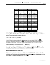
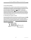
TX Clock Pin Selection (SW17-4)
The primary transmit clock can be derived from either pins Y,AA or pins U,W. If pins Y,AA are
to be the source for primary TX Clock, set SW17-4 to
ONON
ONON
ON. If pins U,W are to be the source for
primary TX & RX Clock, set SW17-4 to
OFFOFF
OFFOFF
OFF.
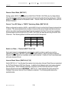
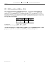
RX Clock Source Selection (SW18-4,5,6)
RX Clock Source is selected by SW18-4, 5 and 6. The following table indicates the source
options provided by the 3040/V35 (CTS MD-V.35/TCB). If the TXC source is pins U,W, both
RXC and TXC will be sourced from pins U,W. When the unit is used in an Async network
select INTERNAL as the source of the RX Clock.
SW18-4 SW18-5 SW18-6 Source
ON ON ON Master
OFF ON ON Port 1
ON OFF ON Port 2
OFF OFF ON Port 3
ON ON OFF Port 4
OFF ON OFF unused
ON OFF OFF unused
OFF OFF OFF Internal
Internal Must Be Selected For
Async Operation