


3040/V35
139001UA
2-7
INSTALLATION AND OPERATIONS MANUAL
SETUP & INSTALLATION
PATTON ELECTRONICS CO.
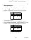
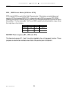
Tail Circuit Buffers (SW16-4)
The 3040/V35 (CTS MD-V.35/TCB) has a Tail Circuit Buffer that is automatically selected
when a Sub-Channel is set as a DTE. The buffer will provide clock synchronization of the data
from the Sub-Channel to the Master Port for Tail Circuit operations. The buffer is de-activated
when the Sub-Channel is configured as a DCE. When operating in an asynchronous
environment the Buffer must be bypassed. To bypass the buffer in a synchronous or
asynchronous application, set switch SW16-4 to
OFFOFF
OFFOFF
OFF (ASYNC). For normal operation in a
synchronous environment set SW16-4 to
ONON
ONON
ON (SYNC). When using a tail circuit modem with
the 3040/V35 (CTS MD-V.35/TCB), the modem connected to the Sub-Channel, should be set
to External Transmit Clocking. The modem at the remote end of the connection should be set
to RX-TX Clocking or Slaved TX Clock. This will insure the same clock is present throughout
the network and clock slippage will not occur.
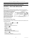
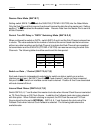
Port DCE/DTE Selection (SW5 thru SW14)
Slide switches SW5 through SW14 are used to configure DTE/DCE for each port. Slide Both
switches associated with a port to the same position.
Example:
If connecting a modem (DCE
Device) to the PORT, then the port should be configured as a DTE interface. Slide both
switches to the DTE position toward the interface connector. If connecting a terminal (DTE) to
the Sub-Channel, the port should be configured as a DCE. Slide both switched to the DCE
position away from the interface connector.
The port is always configured opposite to the
interface that is to be connected to it
.
DCE
DCE
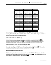
Forced DSR/DTR
J8 thru JP12