


3040/V35
139001UA
iii
INSTALLATION AND OPERATIONS MANUALPATTON ELECTRONICS CO.
Contents
CHAPTER 1 - OPERATION
Channel Clocking ............................................................................................................................... 1-1
Fallback Clocking ............................................................................................................................... 1-1
Channel Interface ............................................................................................................................... 1-1
Anti-streaming .................................................................................................................................... 1-2
Channel Selection Modes .................................................................................................................. 1-2
Channel Tail Circuits ......................................................................................................................... 1-3
Interface Connections ........................................................................................................................ 1-4
Front Panel LEDs .............................................................................................................................. 1-4
Channel Enable / Disable Switches .................................................................................................. 1-4
Power Supply ..................................................................................................................................... 1-4
CHAPTER 2 - SETUP AND INSTALLATION
Power Connection ............................................................................................................................. 2-1
Factory Configuration Switch Settings .............................................................................................. 2-1
Disassembly ...................................................................................................................................... 2-2
Installation .......................................................................................................................................... 2-2
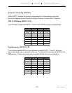
Equipment Grounding (SW15-1) ....................................................................................................... 2-3
RTS To CTS Delay (SW16-1,2,3) ..................................................................................................... 2-3
Anti-Streaming (SW18-1,2,3) ............................................................................................................ 2-3
Receive Data Mode (SW18-7) .......................................................................................................... 2-3
Control Turn-Off Delay in “DATA” Switching Mode (SW15-3,4) ....................................................... 2-4
Switch on Data / Control (SW17-5,6,7,8) .......................................................................................... 2-4
Internal Baud Rates (SW15-5,6,7,8) ................................................................................................. 2-4
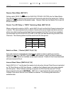
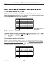
Fallback Clock Enable (SW16-7) ...................................................................................................... 2-5
Fallback Clocking From Sub-Channel 4 (SW16-8) ........................................................................... 2-5
Fallback Mode Selection (SW16-6) ................................................................................................... 2-5
TX Clock Source Selection (SW17-1,2,3) .........................................................................................2-6
TX Clock Pin Selection (SW17-4) ..................................................................................................... 2-6
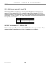
RX Clock Source Selection (SW18-4,5,6) ........................................................................................ 2-6
Tail Circuit Buffers (SW16-4) ............................................................................................................ 2-7
Port DCE/DTE Selection (SW5 thru SW14) ..................................................................................... 2-7
DTR / DSR Forced Active (JP8 thru JP12) ....................................................................................... 2-8
FACTORY Test Jumpers (JP1, JP2 and JP3) .................................................................................. 2-8
APPENDIX
Typical Application .............................................................................................................. A-1
Typical Tail Circuit Configuration ......................................................................................... A-1
Interface Pins Supported ..................................................................................................... A-2
Master DTE / Sub-Channel DTE Interface Flow Diagram .................................................... A-3
Master DTE / Sub-Channel DCE Interface Flow Diagram.................................................... A-3
Master DCE / Sub-Channel DCE Interface Flow Diagram ................................................... A-4
Master DCE / Sub-Channel DTE Interface Flow Diagram.................................................... A-4
TECHNICAL SPECIFICATIONS.......................................................................................... A-5
Strapping Guide .................................................................................................................. A-6