


33
34
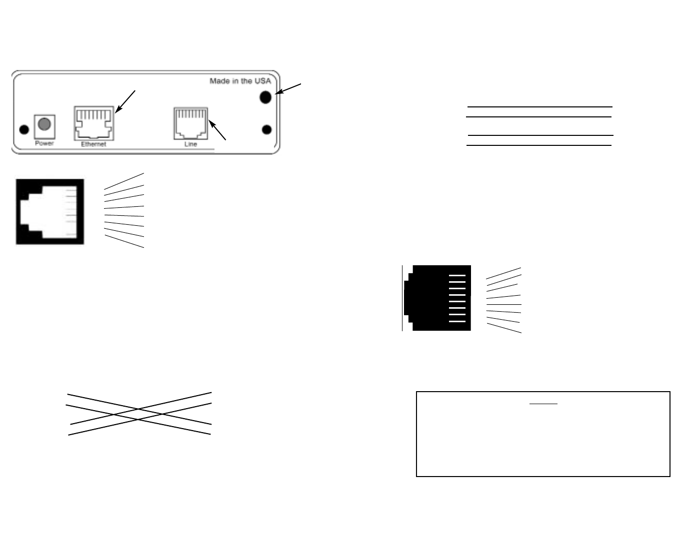
44..00 IINNSSTTAALLLLAATTIIOONN
The Model 2720 is equipped with DTE, network, and power inter-
faces. This section briefly describes connection to each.
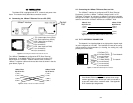
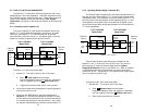
4.1 Connecting the 10Base-T Ethernet Port to a PC (DTE)
The 10Base-T Interface is configured as DTE (Data Terminal
Equipment). If the Model 2720/I is to to connect to another DTE
device such as a 10Base-T network interface card, construct a
10Base-T crossover cable and connect the wires as shown in the dia-
gram below (Figure 4).
10BaseT Port 10Base-T DTE
RJ-45 Pin No. RJ-45 Pin No.
1 (TD+) 1 (TD+)
2 (TD-) 2 (TD-)
3 (RD+) 3 (RD+)
6 (RD-) 6 (RD-)
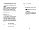
4.2 Connecting the 10Base-T Ethernet Port to a Hub
The 10Base-T interface is configured as DTE (Data Terminal
Equipment), just like a 10Base-T network interface card in a PC.
Therefore, it “expects” to connect to a 10Base-T Hub using a straight-
through RJ-45 cable. Use the diagram below (Figure 9) to construct a
cable to connect the 10 BaseT interface to a 10Base-T Hub.
10BaseT Port 10Base-T Hub
RJ-45 Pin No. RJ-45 Pin No.
1 (TD+) 1 (RD+)
2 (TD-) 2 (RD-)
3 (RD+) 3 (TD+)
6 (RD-) 6 (TD-)
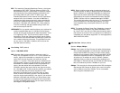
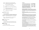
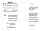
4.3 T1/FT1 INTERFACE CONNECTION
The Network Line Interface Line is an eight position keyed modu-
lar jack configured as a RJ-48C. This interface will need to be config-
ured to match the line parameters (i.e. framing, line coding, etc.) sup-
plied by the central office.
1 TD+ (data output from 2720/I)
2 TD- (data output from 2720/I)
3 RD+ (data input to 2720/I)
4 (no connection)
5 (no connection)
6 RD- (data input to 2720/I)
7 (no connection)
8 (no connection)
1
2
3
4
5
6
7
8
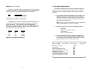
Figure 3: Connecting the 10Base-T Ethernet Port to a PC
Figure 4: 10Base-T Cross-over Cable Connection
Figure 5: Connecting the 10Base-T Ethernet Port to a Hub
Figure 6. Model 2720 twisted pair line interface.
1 RX Data (TIP)
2 RX Data (RING)
3 (no connection)
4 TX Data (TIP)
5 TX Data (RING)
6 (no connection)
7 (no connection)
8 (no connection)
1
2
3
4
5
6
7
8
} From Network
} To network
NOTE:
If the Model 2720 is being used for private short range
modem applications, the twisted pair cable connected to
its port will need to be a crossover cable. See Appendix
D for Interface pin assignments.
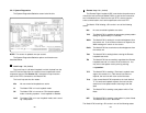
Control
Port
T1 Interface
10BaseT Interface