


5.2 LOOP (V.54 & TELCO) DIAGNOSTICS
The NetLink-T1™ offers three V.54 loop diagnostics and is com-
patible with two Telco loop diagnostics. Use these diagnostics to test
the CSU/DSU and any communication links. These tests can be acti-
vated via the software control port (See Section 3.2.3 System
Diagnostics), via signals on the serial port interface or the front panel
switch.
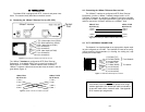
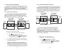
5.2.1 Operating Local Loopback (LL)
The Local Loopback (LL) test checks the operation of the local
NetLink-T1™, and is performed separately on each unit. Any data
sent to the local NetLink-T1™ in this test mode will be echoed
(returned) back to the user device (i.e., characters typed on the key-
board of a terminal will appear on the terminal screen).
To perform a LL test, follow these steps:
1. Activate LL. This may be done in one of two ways:
a. Enter Local Loop from the System
Diagnostics/Statistics menu and toggle the <Spacebar>
until “LL” appears next to the Local Loop option.
b. Toggle the front panel switch to the “Local” position.
2. Verify that the data terminal equipment is operating properly
and can be used for a test.
3. Perform a V.52 BER (bit error rate) test as described in
Section 5.3. If the BER test equipment indicates no faults,
but the data terminal indicates a fault, follow the manufactur-
er’s checkout procedures for the data terminal. Also, check
the interface cable between the terminal and the NetLink-T1.
38
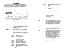
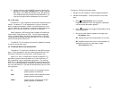
5.2.2 Operating Remote Digital Loopback (RL)
The Remote Digital Loopback (RL) test checks the performance of
both the local and remote NetLink-T1™, as well as the communication
link between them. Any characters sent to the remote NetLink-T1™ in
this test mode will be returned back to the originating device (i.e, char-
acters typed on the keyboard of the local terminal will appear on the
local terminal screen after having been passed to the remote NetLink-
T1™ and looped back).
There are two Remote Loops that can be initiated from the
NetLink-T1 unit: (1) V.54 Loop, and; (2) CSU Loop. The user can
select the type of loop that can be initiated from the System
Diagnostics/Statistics screen or with Switch S1-1. When a loopback
is initiated this is the type of loop that the unit uses to loop up the
remote unit. NOTE: The NetLink-T1 will respond to both loops regard-
less of the state of the RDL Type.
To perform an RDL test, follow these steps:
1. Activate RDL. This may be done in two ways:
a. Enter Remote Loop from the System
Diagnostics/Statistics menu and toggle the <Spacebar>
until “RL” appears next to the Remote Loop option.;
b. Set the front panel switch to ‘Remote’.
37
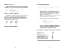
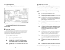
Figure 8. Local Loopback
Ethernet
Device
Ethernet
Device
Receive
Recover
Clocking
Internal
Clocking
Cable Span
T1/FT1 CSU/DSU
Model 2720/I
T1/FT1 CSU/DSU
Model 2720/I
Clock/
Data
Clock/
Data
Clock/
Data
Data
Data
Model 2720/X
Model 2720/I
LLB Initiated
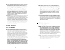
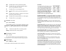
Figure 9. Local Loopback
Ethernet
Device
Ethernet
Device
Receive
Recover
Clocking
Internal
Clocking
Cable Span
T1/FT1 CSU/DSU
Model 2720/I
T1/FT1 CSU/DSU
Model 2720/I
Clock/
Data
Clock/
Data
Clock/
Data
Data
Data
Model 2720/I
RL Initiated
Model 2720/I
b
b
a
a
x