


40
39
2. Perform a bit error rate test (BERT) using the internal V.52
generator (as described in Section 5.3), or using a separate
BER Tester. If the BER test indicates a fault, and the Local
Line Loopback test was successful for both NetLink™s, you
may have a problem with the twisted pair line connection.
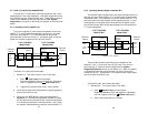
5.2.3 CSU Loop
The NetLink-T1™ also responds to central office initiated loop com-
mands. The NetLink-T1™ will implement the “loop up” command
when it recognizes the pattern “10000” in the data stream for a mini-
mum of 5 seconds. The “loop down” command is implemented by the
pattern “100” in the data stream for a minimum of 5 seconds.
When operating in ESF framing mode, loopback commands are
issued via the Facility Data Link (FDL). The line loop message will
cause a loop back before data enters the framer portion of the CSU.
The payload loop message will cause the NetLink-T1™ to loop data
after the framer portion of the CSU.
The NetLink-T1™ will respond to Universal Loopback De-activate
to clear all central office loops.
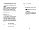
5.3 BIT ERROR RATE (V.52) DIAGNOSTICS
The NetLink-T1™ offers three V.52 Bit Error Rate (BER) test pat-
terns. These test patterns may be invoked along with the LAL and
RDL tests to evaluate the unit(s) and the communication links.
When a 511, 2047, or QRSS test is invoked, the NetLink-T1™
generates a pseudo-random bit pattern of 511 bits, 2047 bits or 2
20
bits, respectively, using a mathematical polynomial. The receiving
NetLink- T1™ then decodes the received bits using the same polyno-
mial. If the received bits match the agreed upon pseudo-random pat-
tern, then the NetLink-T1™(s) and the communication link(s) are func-
tioning properly.
511 Initiates a built-in 511 bit pseudo-random
pattern generator and detector.
2047 Initiates a built-in 2047 bit pseudo-random
pattern generator and detector.
QRSS Initiates a built-in 2
20
bit pseudo-random
pattern generator and detector.
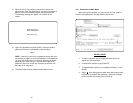
To perform a V.52 test, follow these steps:
1. Activate the local loopback or remote loopback diagnostic.
2. Activate the test pattern. This may be done in one of two
ways:
a. Enter Selected Pattern from the System
Diagnostics/Statistics menu and toggle the <Spacebar>
until the desired test pattern appears.
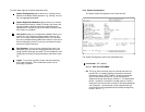
b. Enter Test Pattern and toggle the [Spacebar] to send
the selected pattern.
c. One of two result codes will appear to the right of the
Test Pattern listing:
OK Indicates that the received test pattern is error-free.
BE Indicates that there are errors in the test pattern (to
deliberately insert errors in the pattern, toggle
Error Insertion to ON).
c
e