


11
12
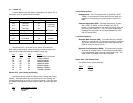
Switch S2-6 and S2-7: Clock Mode
Set Switch S2-6 and S2-7 to determine the 2720’s transmitter tim-
ing.
S2-6
S2-7 Clock Mode
Off Off
Network Clock
. Transmitter timing is
derived from the received line signal.
On Off
Internal Clock
. Transmitter clock is
derived from an internal oscillator.
NOTE 1: When using the Model 2720 as a high-speed short
range modem, one unit of the link must be configured in Internal
Clock mode, and the opposite end unit must be configured for
Network Clock mode.
If the ERR LED on the front of the unit is flashing (or on) it could
be an indication of a clocking problem. Double check your clock
mode settings and Tx Clock Invert S1-3 settings.
Switch S2-8 Reserved
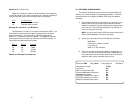
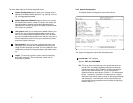
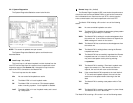
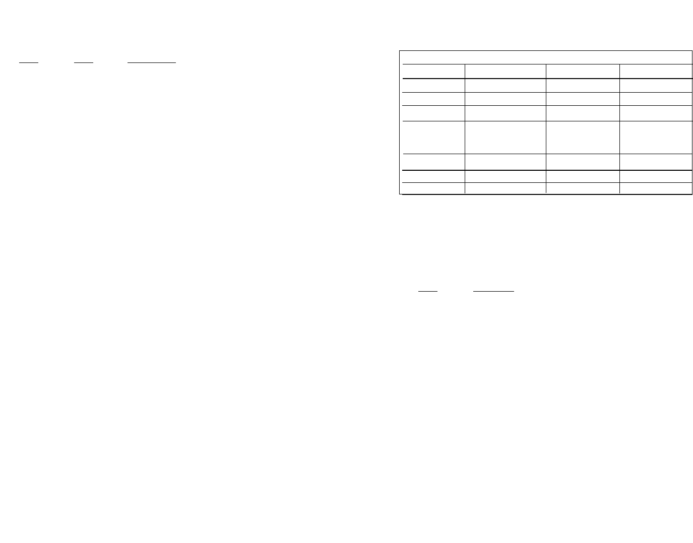
3.1.2 Switch S1
The chart below shows the default configurations for Switch S1. A
description of all S1 options follows this table.
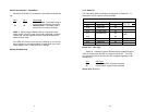
Switch S1-1: RDL Type
Switch S1-1 selects the type of Remote Digital Loopback that the
2720 will initiate when the RDL is initiated from this unit. The 2720
will respond to both the V54 and the CSU loopback regardless of the
setting of S1-1
S1-1
RDL Type
On Initiate a V.54 RDL loop when selected
Off Initiate a CSU loopback when selected
Switch S1-2: Reserved
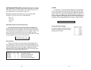
S1 SUMMARY TABE
Position Function Factory Default Selected Option
S1-1
RDL Type
On
S1-2
Reserved
On
S1-3
Tx Clock Invert
Off
S1-4
Line Build Out
Off
S1-5 Off
S1-6
Reserved
Off
S1-7
Reserved
Off
S1-8 Reserved Off
V.54 RDL
Normal
0dB