


4 Pelco Manual C1503M (11/99)
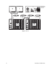
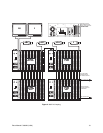
6. Install the system CM9760-CC1 CPU and CM9760-MXB matrix bays near each other.
Note that each CM9760-MXB has a unique label for identifying the bay location in the
installation. This ID information is important in ensuring correct video and data connec-
tions.
7. Install any system peripherals in a convenient location.
8. Locate the CM9760-KBD system keyboard(s), CM9505-UPS power supply(s), and the
two RJ-45 data cables supplied with each keyboard.
9. Connect all power line cords to the equipment. Do not apply power to the equip-
ment at this time.
SYSTEM DATA CONNECTIONS
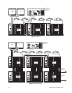
1. CM9760-CC1
This is the main system controller, often called the CPU.
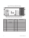
a. Copy the supplied system port settings from the System 9760 Factory Default
Port Settings to the System Port Settings Table in the appendix of this installation
guide.
b. Enter the label information from each matrix bay in the Description section (to
avoid confusion after completing the installation).
c. Update this table as the installation proceeds.
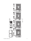
2. CM9760-MXB
This is the video matrix (switching) bay that contains the video input, output modules,
and bay controller module.
a. Follow the System Port Settings Table and connect the CM9760-CC1 to the
CM9760-MXB bays using the supplied RJ-45 data cables.
b. Be sure to match the matrix bay label to the CM9760-CC1’s port.
3. CM9760-KBD
This is the system keyboard for operator control commands.
a. Locate the RJ-45 data cable labeled “STRAIGHT.” Connect one end to the COM1
input on the bottom of the keyboard; connect the other end to the KEYBOARD in-
put on the CM9505-UPS power supply.
b. Locate the cable labeled “REVERSED.” Identify the keyboard on the System Port
Settings Table. Connect one end of this cable to the appropriate data port on the
CM9760-CC1; connect the other end to the CARD CAGE input on the CM9505-
UPS.
4. External PC/CM9760-MGR
The CM9760-CC1 provides two 9-pin sub-miniature D connectors used for standard
RS-232 communications with the CPU. COM1 is set at the factory for use with the
CM9760-MGR program used for system programming.
a. Connect one end of a standard 9-pin sub-D cable (not supplied) to the CM9760-
CC1 and the other end to the external PC.
b. Be sure the Com port settings on the PC match the settings for COM1 on the
CM9760-CC1.
c. Refer to the
Hardware Installation
section in the CM9760-MGR System 9760 Ad-
ministrative Software Manual.