


Pelco Manual C1503M (11/99) 5
ADDITIONAL HOOKUP INFORMATION
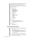
• Comms File
The Comms Setup File contains information about the equipment that is attached to
your system. Access the Comms dialog box by clicking on the Comms tab in the Setup
9760 Configuration dialog box. Refer to the
Comms Setup File (.SCP File)
section in
the CM9760-MGR System 9760 Administrative Software Manual for information.
• Pan And Tilt Receivers and Domes
Each port can have up to 16 receivers or domes when using hardwired RS-422 com-
munications connected in a daisy chain configuration.
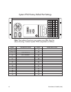
• Ports
Use the System Port Settings Table to determine which ports are not in use. When set-
ting up pan and tilt devices for use with the System 9760, edit the Comms file using
Pin #9 as the equipment number. Be sure the assigned port’s baud rate and parity
match that of the pan and tilt receiver. Refer to the
Comms Setup File (.SCP File)
sec-
tion in the CM9760-MGR System 9760 Administrative Software Manual.
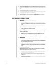
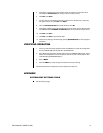
• Peripheral Equipment
Refer to the specific user manual for a description of each device. An RJ-45 data cable
is included with each device. Using the Factory Default Port Settings page and the
device’s interconnect cable, connect all peripheral equipment to its appropriate data
port. If the device is not shown on the Factory Default Port Settings page, refer to the
major section
Configuring the System 9760 with the Pelco Window Set 9760
in the
CM9760-MGR System 9760 Administrative Software Manual. Also, refer to
Video In-
puts
and
Video Outupts
sections for information on connecting video sources and out-
puts.
• CM9760-NW1
This CPU serves as a communications hub when networking two or more System
9760s. This unit includes its own Factory Default Settings table. Use both tables to de-
termine which ports are used for data interconnection between the CM9760-CC1s and
the CM9760-NW1.
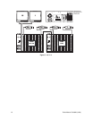
SYSTEM VIDEO CONNECTIONS
For best results, use crimp-on BNCs only. Do not use screw-on BNCs–these typically do
not provide adequate ground and signal connections.
DEFINITIONS
Bay Capacity: A single CM9760-MXB can support up to 256 inputs (in increments of
16) and 16 outputs (in increments of 4).
Side Framing: A technique to expand the matrix video inputs beyond 256.
Down Framing: A technique to expand the matrix video outputs beyond 16.
Video Tie Lines: A method for connecting side-framed matrix bays together and networked
systems together. A video tie line is a video output from one bay con-
nected to the video input of another. In a networked system, a tie line
provides the video path necessary to view video from a remote node.
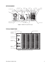
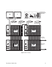
VIDEO INPUTS
SINGLE-BAY SYSTEMS
Refer to the sample drawings in the appendix. Connect all video sources (cameras, VCRs,
etc.) to the video input BNCs at the rear of the CM9760-MXB(s). Connect video 1 to the BNC
marked “1,” video 2 to the second BNC directly below “1,” and so on until all video cables
are connected. If the system is set up for looping, terminate the looped output at 75 ohms.