


6 Pelco Manual C1503M (11/99)
MULTI-BAY SYSTEMS
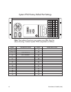
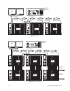
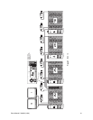
1. Down-Framing – For systems with more than 16 monitor outputs, you must pas-
sively loop the video from the first CM9760-MXB to the second CM9760-MXB for the
next 16 monitors. The best location for the second bay is below the first bay, as shown
in the system drawing. Connect the supplied multi-coax ribbon cable from the bottom
of the first bay to the down-frame loop input of the second. Continue in this manner
connecting all down-framing bays.
2. Video-Looping – If your system is configured for video looping, properly terminate
the video cable at the last connection with 75 ohm.
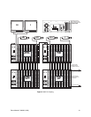
3. Side-Framing – For systems with more than 256 video inputs, connect the 16 video
outputs from the second matrix bay to the first 16 video inputs of the first bay. The best
location for the second bay is next to the first bay on the same level, as shown in the
system drawing. Continue in this manner connecting all side-framing bays.
VIDEO OUTPUTS
Connect all video outputs from the CM9760-MXB to their desired device (that is, monitors,
printers, VCRs, etc.). Terminate the device at 75 ohms.
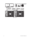
NETWORKING
For networked systems, refer to the system drawing to determine which monitor outputs
and camera inputs were assigned as video tie lines. Connect the monitor outputs assigned
as tie lines of one system to the video inputs assigned as tie lines of the other, and vice
versa.
SYSTEM PROGRAMMING
Apply power to the CM9760-CC1, keyboard, monitor, and PC (as appropriate to the method
of programming) for system programming.
The two methods of programming the CM9760 system are as follows:
CM9760-MGR
This is the preferred programming method. It requires an external IBM-compatible PC run-
ning Windows
®
95 and the supplied CM9760-MGR Manager Program. Pelco recommends
using an AT-type keyboard and VGA monitor. All system programming can be done off-site
and later downloaded (transferred) to the CM9760-CC1 by writing flat files (see the
DOS
section for an explanation of flat files). Or you can do direct “live” programming through an
RS-232 connection between the PC and the CM9760-CC1. See the
Installing the 9760-
MGR Software
section in the CM9760-MGR System 9760 Administrative Software Manual
for details on installing the CM9760-MGR program.
The sections
Transfer Files from CM9760-CC1 to CM9760-MGR, Transfer Files from
CM9760-MGR to 3.5-Inch Floppy Disk
, and
Transfer Files from 3.5-Inch Floppy Disk to
CM9760-CC1
that follow in this document pertain to this method.
SET 9750
This is the second programming method. The DOS-based SET 9750 program on the
CM9760-CC1 hard drive requires a VGA monitor and AT-type keyboard connected directly
to the CM9760-CC1. See the
Configuring the System 9760 with the Pelco Windows SET
9760
section in the CM9760-MGR System 9760 Administrative Software Manual.
WARNING:
After
the Windows
manager program
(CM9760-MGR) is used to
create or edit configuration
files, the SET 9750 program
cannot be used. In other
words, the System 9760-
MGR flat files are not
backward compatible with
SET 9750.