


C841M-A (7/02) 5
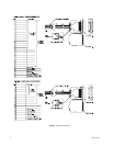
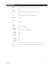
Table A. Jumper Settings - VA6200 Series
Jumper Position Function
JP1 - JP20 A Camera input terminated (75 ohms)
B Camera input looping (high impedance)
JP23, JP24, JP25, JP26, JP28, JP31 A Camera titles on Monitor 1
B Camera titles on Monitor 2
JP29 or JP32 A PAL video standard
B NTSC video standard
JP30 or JP33 A Standard character set
B Extended character set
Standard character set: 0-9, A-Z, punctuation
Extended character set: Standard character set plus lower case letters, symbols, and
kanji and katakana characters
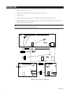
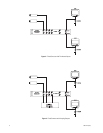
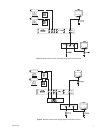
6. Wire the alarm inputs, alarm output, and external trigger directly. Refer to Figure 6 to build a cable using either the 15-pin
or 25-pin D-type mating connector that is supplied with the switcher.
The alarm inputs require a ground signal to activate them. There is one alarm input for each camera. For example, an
alarm on input 5 directs the switcher to select camera 5.
The alarm output is a relay with normally open (N.O.) and normally closed (N.C.) contacts. This connection is intended to
activate an external device, such as a VCR, when there is an alarm. Refer to the
Specifications
section for the voltage and
current ratings of the relay.
The external trigger is an input connection. It is for use with time-lapse recorders that have an external trigger output to
control the sequencing of cameras.
7. Plug in the power cord. The switcher begins operating.
8. Synchronize the cameras if there is vertical roll when switching between cameras. Refer to the instruction manuals
supplied with the cameras.
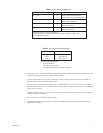
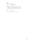
Table B. Video Coaxial Cable Requirements
Cable Type* Maximum Distance
RG59/U 750 ft (229 m)
RG6/U 1,000 ft (305 m)
RG11/U 1,500 ft (457 m)
*Minimum cable requirements:
75 ohms impedance
All-copper center conductor
All-copper braided shield with 95% braid coverage