


40 Pelco Manual C523M-H (6/05)
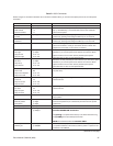
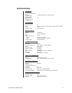
Table E. Solutions To Common Problems
Problem Remedy
CM6700 does not have power. Make sure the power cord is plugged in.
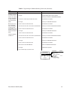
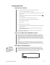
Check the fuse. Refer to Figure 6 for the fuse location.
You can see some cameras and not others Confirm that the camera is properly connected and has power.
from your location.
The keyboard and monitor may have been denied access to the cameras.
The CM6700 does not respond to key- Confirm that the monitor the keyboard is addressing is the same as the monitor in
board commands. front of you.
Pressing the PGM key displays a P on the Confirm that the keyboard transformer is plugged in and all electrical connections
keyboard LED but the Password menu are in order.
does not appear on the menu.
Confirm that the monitor the keyboard is addressing is the same as the monitor in
front of you.
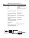
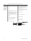
Upon initial system startup, the alpha- Jumper JP17 on the motherboard is in the wrong position. Remove the cover and
numeric monitor display is in the middle change JP17 to the opposite position. Instructions for switching video termination
of the screen or is not seen. jumpers in the
Set Options
section are a similar process.
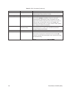
Keyboards do not function after installation
Confirm that all wiring is correct and that keyboards have power and are connected.
and initial power-up.
Confirm that all keyboards are addressed differently.
Previous system control has been lost. First, try initializing the keyboard by entering the monitor number followed by
pressing the MON key. If this does not restore control…
Second, try unplugging the data cable from the rear of the keyboard and then
plugging it back in. Then re-initialize the keyboard. If this does not restore control…
Third, power down the CM6700, power back up, and then re-initialize keyboards.
If this does not restore control…
Fourth, perform a software reset (refer to
Performing a Software Reset
in this
section). If this does not restore control, call Pelco at 1-800-289-9100.
Cannot gain keyboard and ASCII port PTZ You must wait at least five seconds after a separate user has stopped before you
control after another user has stopped can gain control.
controlling.
The unit malfunctions and you cannot Perform a software reset (refer to
Performing a Software Reset
in this
restore it to satisfactory operation. section).
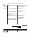
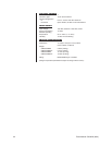
The keyboard transformer must be If a 12 VAC transformer is unavailable, you can use a 12 VDC transformer.
replaced. Polarity is unimportant when wiring the transformer to the wall jack.
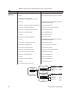
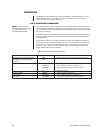
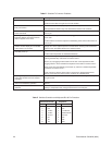
Table F. Switcher/Controller and Keyboard RJ-45 Pin Functions
Switcher/Controller Keyboards
Pin Function Pin Function
1 RX+ 1 TX+
2 RX- 2 TX-
3 12 VAC 3 12 VAC/DC
4 12 VAC 4 NON-POLAR
5 Ground 5 Ground
6NC 6NC
7 TX- 7 RX-
8 TX+ 8 RX+
NC = No connection