


SMART I/O User’s Manual
March 12, 1996
©1996 PEP Modular Computers GmbH
Page 4 - 22
Chapter 4 Digital Modules
4.2.6 Configuration
There are no jumpers to configure on the SM-DOUT1.
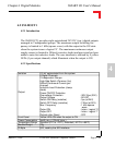
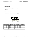
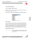
4.2.7 Pinouts
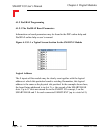
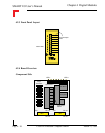
Screw Terminal Pinouts
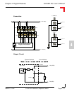
The following shows the pinout/signal relationship for the SM-DOUT1
when connected to a particular screw terminal block.
Pin 1
Pin 2
Pin 13
Pin 14
Pin Nr. Signal Description Pin Nr. Signal Description
1 V01EXT Vcc for channels 0 & 1 2 V45EXT Vcc for channels 4 & 5
3 OUT0 Output 0 4 OUT4 Output 4
5 OUT1 Output 1 6 OUT5 Output5
7 V23EXT Vcc for channels 2 & 3 8 V67EXT Vcc for channels 6 & 7
9 OUT2 Output 2 10 OUT6 Output 6
11 OUT3 Output 3 12 OUT7 Output 7
13 G03EXT GND for channels 0..3 14 G47EXT GND for channels 4..7