


SMART I/O User’s Manual
March 12, 1996
©1996 PEP Modular Computers GmbH
Page 4 - 36
Chapter 4 Digital Modules
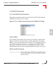
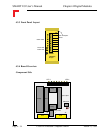
4.3.6 Configuration
Jumper J1 - EEPROM Protection
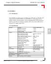
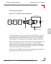
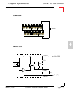
4.3.7 Pinouts
Screw Terminal Pinouts
The following shows the pinout/signal relationship for the SM-REL1 when
connected to a particular screw terminal block.
Pin 1
Pin 2
Pin 13
Pin 14
Pin Nr. Signal Description Pin Nr. Signal Description
1 NO0 N/O Relay 0 Conn. 2 COM0 Relay 0 Common Conn.
3 NO1 N/O Relay 1 Conn. 4 COM1 Relay 1 Common Conn.
5 NO2 N/O Relay 2 Conn. 6 COM2 Relay 2 Common Conn.
7 NO3 N/O Relay 3 Conn. 8 COM3 Relay 3 Common Conn.
9 NO4 N/O Relay 4 Conn. 10 COM4 Relay 4 Common Conn.
11 NO5 N/O Relay 5 Conn. 12 COM5 Relay 5 Common Conn.
13 VCCEXT External 24V DC VCC 14 GNDEXT External GND
Jumper Settings Description
J1
set EEPROM is not hardware write protected
open EEPROM is hardware write protected