


SMART I/O User’s Manual
October 01, 1996
©1996 PEP Modular Computers GmbH
Page 5 - 92
Chapter 5 Analog Modules
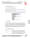
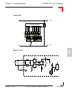
5.4.6 Configuration
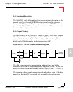
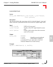
Although the SM-ADC1 has one solder jumper (J2) for EEPROM configura-
tion, the user should not interfere with it.
Jumper J4 likewise should not be interfered with as it is factory set at the
time of ordering and controls the unipolar/bipolar mode of ADC operation .
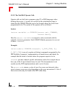
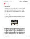
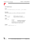
5.4.7 Pinouts
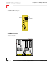
Screw Terminal Pinouts
The following shows the pinout/signal relationship for the SM-ADC1 when
connected to a particular screw terminal block.
Pin 1
Pin 2
Pin 13
Pin 14
Pin Nr. Signal Description Pin Nr. Signal Description
1 IN0+ Analog Input Ch. 0+ 2 IN3+ Analog Input Ch. 3+
3 IN0- Analog Input Ch. 0- 4 IN3- Analog Input Ch. 3-
5 AGND Analog GND 6 AGND Analog GND
7 IN1+ Analog Input Ch. 1+ 8 IN4+ Analog Input Ch. 4+
9 IN1- Analog Input Ch. 1- 10 IN4- Analog Input Ch. 4-
11 IN2+ Analog Input Ch. 2+ 12 IN5+ Analog Input Ch. 5+
13 IN2- Analog Input Ch. 2- 14 IN5- Analog Input Ch. 5-