


SMART I/O User’s Manual
©1996 PEP Modular Computers GmbHMarch 12, 1996 Page 2 - 13
2
Chapter 2 SMART-BASE
+Vcc (24V)
Gnd (common)
Digital
Input
Low
Pass
Filter
Input
Circuit
Timer I/O
TIN
+Vcc (24V)
Gnd (common)
GATE
Low
Pass
Filter
Input
Circuit
1
4
3
1
6
5
TINGATE
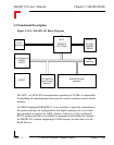
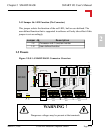
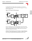
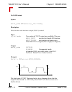
To understand the functionality of the counter/timer, it is necessary to
understand the purpose of TIN, TOUT and TGATE. Figure 2.5.3.1 shows
the block diagram of TIN.
Figure: 2.5.3.1 Timer I/O (TIN) Schematic
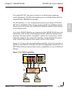
The I/O Controller timer is used for the generation of the TOUT and TIN
functions with the three timer I/O lines being fully isolated from the system.
The internal clock of the timer/counter is 6MHz and can be prescaled to
enable lower frequencies as necessary.
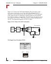
With the GATE permanently active (relay closed), every pulse detected on
the TIN line will be acknowledged up to a frequency of 20kHz. Otherwise,
TIN will only be recognized for the duration that the GATE is active.