


SMART I/O User’s Manual
October 01, 1996
©1996 PEP Modular Computers GmbH
Page 5 - 110
Chapter 5 Analog Modules
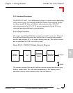
5.5.6 Configuration
Although the SM-DAC1 has one solder jumper for EEPROM configuration,
the user should not interfere with it.
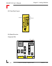
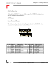
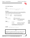
5.5.7 Pinouts
Screw Terminal Pinouts
The following shows the pinout/signal relationship for the SM-DAC1 when
connected to a particular screw terminal block.
Pin 1
Pin 2
Pin 13
Pin 14
Pin Nr. Signal Description Pin Nr. Signal Description
1 OUT0 Analog Output Ch. 0 2 OUT3 Analog Output Ch. 3
3 AGND Analog GND 4 AGND Analog GND
5 OUT1 Analog Output Ch. 1 6 OUT4 Analog Output Ch. 4
7 AGND Analog GND 8 AGND Analog GND
9 OUT2 Analog Output Ch. 2 10 OUT5 Analog Output Ch. 5
11 AGND Analog GND 12 AGND Analog GND
13 AGND Analog GND 14 AGND Analog GND