


UltraPort Serial Adaptors User Guide
Host card back panel connectors and pinouts
Page 105
Chapter 3 Cabling information
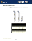
RJ45 back panel connectors and pinout
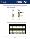
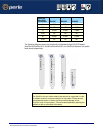
The following diagram shows the UltraPort2 Express, UltraPort4/UltraPort4 SI RJ-45 and
UltraPort4 Express cards back panel.
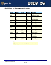
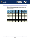
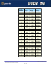
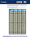
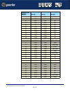
The connector pinout for each RJ45 socket fitted to theUltraPort2 Express, UltraPort4,
UltraPort4 SI, and UltraPort4 Express cards are as follows:
RJ45 10-pin RJ45 8-pin EIA-232 EIA-422 EIA-485
1 N/A RI RTS+
2 1 DCD CTS- NC
3 2 RTS RTS- NC
4 3 DSR RXD- RXD-
5 4 TXD TXD- TXD-/RXD-
6 5 RXD RXD+ RXD+
7 6 S-GND S-GND S-GND
8 7 CTS CTS+ NC
9 8 DTR TXD+ TXD+/RXD+
10 N/A
Shell Shell C-GND C-GND C-GND