


16 / 58
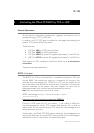
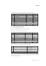
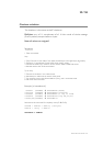
To be able to do all of these 3 sequences, use this command:
Byte# Number of bits Example
0x00 I2CRWwithAck (0x0007) 16 bits 0x0007
0x02 TransactionID 16 bits 0x1B34
0x04 LengthOfParameters (X + 3) 16 bits 0x0005
0x06 7 bits Address (bit 7 = 0) 8 bits 0x28
0x07 X (number of bytes to write) 8 bits 0x02
0x08 xBytes X bytes 0xAF1D
…. Y (number of bytes to read) 8 bits 0x05
The four previous entries can be replicated to access the same or other I2C slaves within this
command sequence.
Checksum 16 bits 0x…
If X = 0, the Read method is used.
If Y = 0, the Write method is used.
If X & Y ≠ 0, the Read after Write method is used.
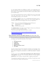
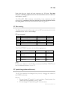
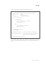
The answer sequence is the following one:
Byte# Number of bits Example
0x00 I2CReadAnswer (0x0008) 16 bits 0x0008
0x02 TransactionID (same as
demand)
16 bits 0x1254
0x04 Number of bytes in answer 16 bits 0x0005
0x06 Answer bytes Y bytes 0x1A25…
… Ack state of the I2C com. 1 byte 0x87
If the same or other I2C slave have been accessed in the command, the answer bytes and ack
state is added here.
… Checksum 16 bits 0x…
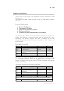
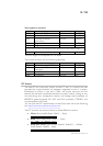
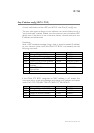
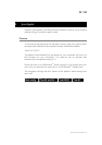
The "Ack state" byte is composed of the following bits:
0 Address ack in write sequence 0 = No answer to this address
1 = ack received
1 Bytes written ack (each byte was acked) 0 = Bytes not acknowledged
1 = ack received
2 Address ack in read sequence 0 = No answer to this address
1 = ack received
3-6 Reserved -
7 Must be always 1 1
The user can use these bits to check for the presence of his I2C devices and
monitor hardware issues.
FMod-TCP User Manual v.2.8