


8 / 58
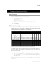
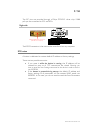
See page 9 to know how the SOS button works.
Two LEDs illuminate the SOS button and the displayed color as the
following meanings:
Green Everything is normal.
Red There is an error. See Warning register to know the
source of the error.
Red-Green The device found another one with the same IP address
er device and rebo t the
FMod-TCP BOX.
blinking on the network. Disable the oth o
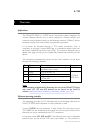
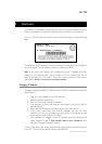
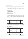
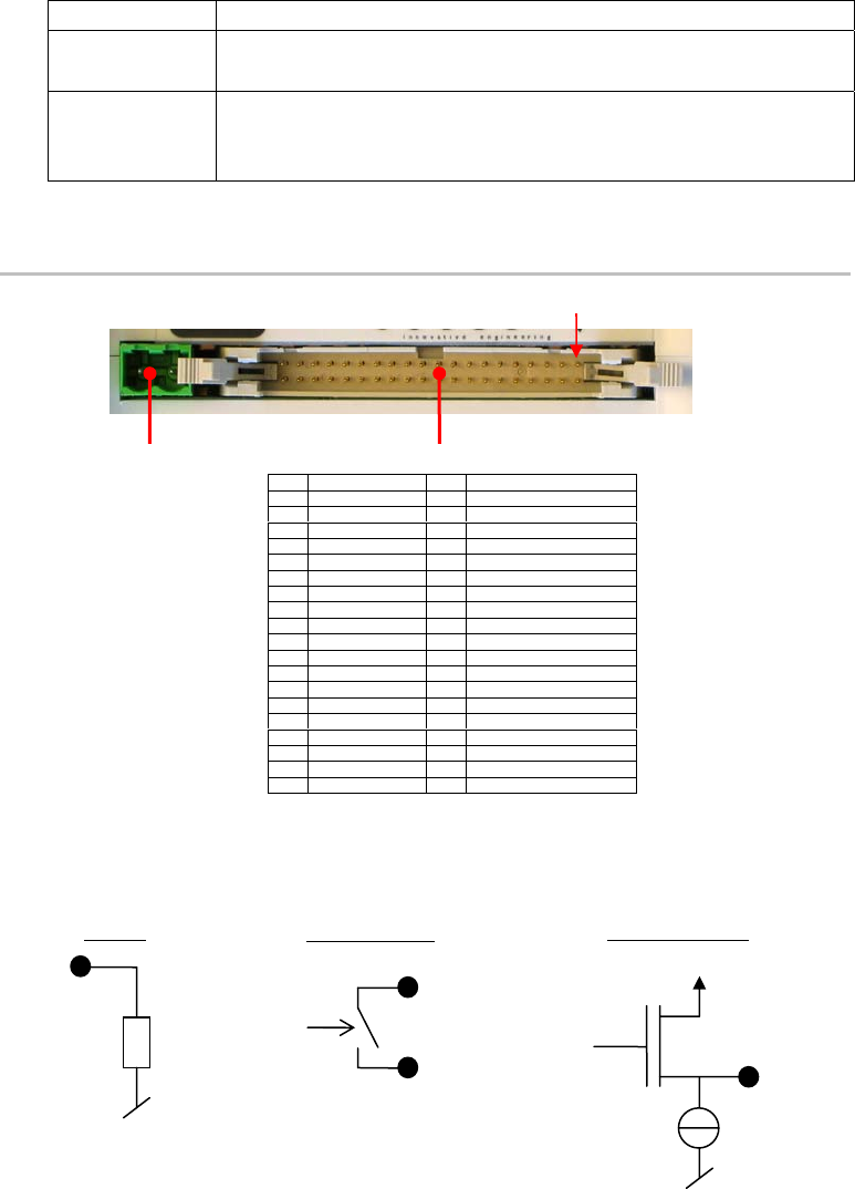
Left side
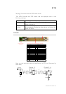
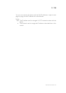
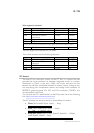
Here are the equivalent electrical specif s of I/O pins (illustra
black dots):
6 Input 6 26 Output 11
7 Input 7 27 Output 10
8 Input 8 28 Output 9
9 Input 9 29 Output 8
10 Input 10 30 Output 7
11 Input 11 31 Output 6
12 Input 12 32 Output 5
13 Input 13 33 Output 4
14 Input 14 34 Output 3
15 Input 15 35 Output 2 B (relay 2)
16 Input 16 36 Output 2 A (relay 2)
18 GND 38 Output 1 A (relay 1)
(SDA) e (max 1A)
a
a
Do not supply the device throu s r connector.
Preliminary
Inputs
Outputs 3-16
Outputs 1-2
V
power
~47kΩ
ication ted by
Power connector
12 – 32 VDC
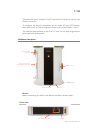
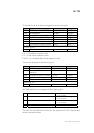
1
st
pin
Inputs, Outputs, I2C, Supply voltage, 5V and GND
1 Input 1 21 Output 16
2 Input 2 22 Output 15
3 Input 3 23 Output 14
4 Input 4 24 Output 13
5 Input 5 25 Output 12
17 +5V 37 Output 1 B (relay 1)
19 I2C clock (SCL) 39 Supply GND
20 I2C data 40 Supply voltag
gh thi pin. Use powe
A
B
2mA
FMod-TCP User Manual v.2.8