


1996 Dec 12 14
Philips Semiconductors Product specification
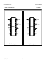
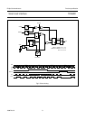
Smart card interface TDA8001
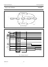
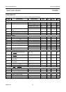
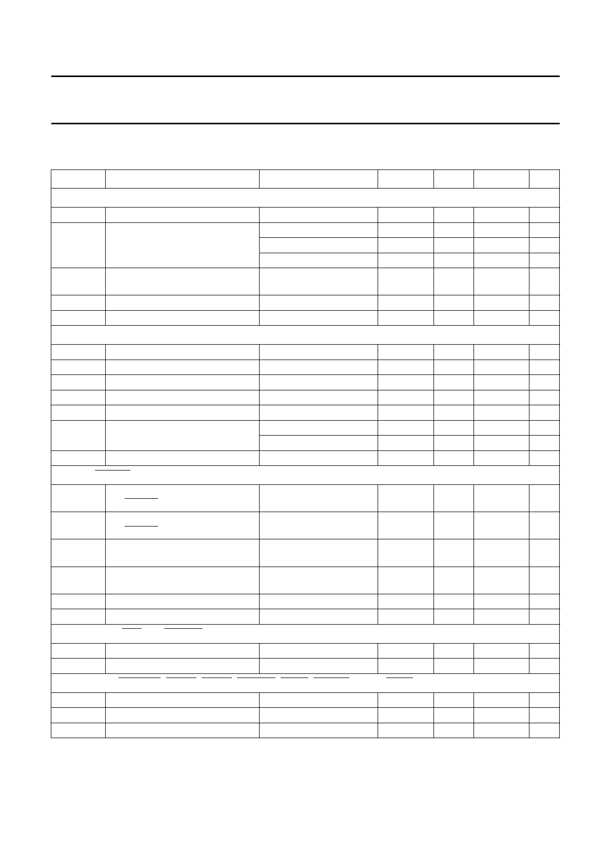
CHARACTERISTICS
V
DD
=12V; V
H
= 25 V; V
SUP
=5V; T
amb
=25°C; unless otherwise specified.
SYMBOL PARAMETER CONDITIONS MIN. TYP. MAX. UNIT
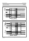
Supply
V
DD
supply voltage 6.7 − 18 V
I
DD
supply current idle mode; V
DD
= 8 V 20 30 38 mA
idle mode; V
DD
= 18V223442mA
active mode; unloaded 35 45 55 mA
V
th1
threshold voltage for power-on
reset
− 3.0 4.0 V
V
th4
threshold voltage on V
DD
(falling) 6.0 − 6.5 V
V
hys4
hysteresis on V
th4
50 − 200 mV
Voltage supervisor
V
SUP
voltage supply for the supervisor − 5.0 − V
I
SUP
input current at V
SUP
− 1.8 2.4 mA
V
th2
threshold voltage on V
SUP
(falling) 4.5 − 4.72 V
V
hys2
hysteresis on V
th2
10 − 80 mV
V
th3
threshold voltage on DELAY 2.35 − 2.65 V
I
DEL
output current at DELAY pin grounded (charge) −5 −−2 µA
V
DEL
= 4 V (discharge) 6 −− mA
V
DEL
voltage on pin DELAY −−3.5 V
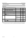
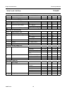
ALARM,
ALARM (open-collector outputs)
I
OH
HIGH level output current on
pin ALARM
V
OH
= 5V −−25 µA
V
OL
LOW level output voltage on
pin ALARM
I
OL
= 2mA −−0.4 V
I
OL
LOW level output current on
pin ALARM
V
OL
= 0V −−−25 µA
V
OH
HIGH level output voltage on
pin ALARM
I
OH
=−2mA V
SUP
− 1 −− V
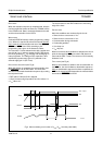
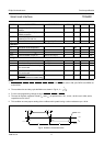
t
d
delay between V
SUP
and ALARM C
DEL
= 47 nF; see Fig.4 −−10 µs
t
pulse
ALARM pulse width C
DEL
= 47 nF 15 − 50 ms
Interrupt lines
OFF and DETECT (open-collector)
I
OH
HIGH level output current V
OH
= 5V −−25 µA
V
OL
LOW level output voltage I
OL
= 1mA −−0.4 V
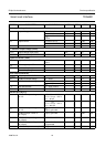
Logic inputs (
CMDVCC, VPP21, VPP15, VPP12.5, CMD7, CMD3.5, PRES, PRES and RSTIN); note 1
V
IL
LOW level input voltage −−0.8 V
V
IH
HIGH level input voltage 1.5 −− V
I
IL
LOW level input current V
IL
= 0V −−−10 µA