


LC1200R User’s Guide
021-0183-00 Rev A 14 of 29
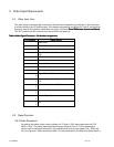
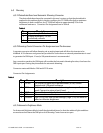
4.2.3
Mode Detection
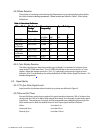
The polarity of incoming horizontal/vertical frequencies and synchronization pulses define
the video resolution
being presented. Video modes are listed in Table 5 Video Mode
Definitions
.
Table
Table Table
Table 5
55
5 Video Mode Definitions
Video Mode Definitions Video Mode Definitions
Video Mode Definitions
Video Mode
Video ModeVideo Mode
Video Mode
Displayed
Displayed Displayed
Displayed
Image
Image Image
Image
Resolution
ResolutionResolution
Resolution
Scanning
Scanning Scanning
Scanning
Frequency)
Frequency)Frequency)
Frequency)
Sync Polarity
Sync PolaritySync Polarity
Sync Polarity
Horizon
tal (KHz)
Vertical
(Hz)
Horizont
al
Vertic
al
IBM VGA 640 x 400 31.468 70 - +
IBM VGA 640 x 480 31.468 60 - -
IBM VGA
w/Border
656 x 496 31.468 60 -
-
IBM VGA 720 x 400 31.468 70 - -
IBM VGA
w/Border
738 x 414 31.468 70
VESA 800 x 600 48.077 72 + +
VESA 1024 x 768 56.48 70 - -
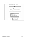
4.2.4
Color Display Detection
The video signal source determines which type of display is connected to it based on the
state of the LC1200R sense lines. The LC1200R will indicate to the source that it is a "color
display" when the monitor sense line 1 (Pin 11) is physically connected to signal ground
reference (Pin 10) as defined by the wiring definitions ofTable 4 Video Signal Connector – Pin
Number Assignments
.
4.3 Signal Quality
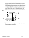
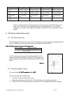
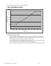
4.3.1
TTL Sync Pulse Signal Levels
Input levels for the horizontal and vertical sync pulses are defined in Figure 5.
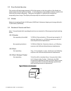
4.3.2
Rise and Fall Times
Rise and fall times are the times required for signal transitions between 10% of Vs above low
steady level and 10% of Vs below high steady level where Vs is the peak-to-peak video input
signal level. The overshoot, if present, shall be exempted from establishing these high/low
levels referenced in. Both rise and fall times of each input signal shall be as follows:
Video: Less than 5-ns
Horizontal Sync: Less than 50-ns
Vertical Sync: Less than 100-ns