


LC1200R User’s Guide
021-0183-00 Rev A 16 of 29
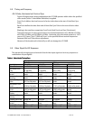
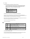
Pulse
Vertical Front
Porch 0.381 ms 12 lines 0.318 ms 10 lines 0.770 ms 37 lines 0.053 ms 3 lines
Vertical Back
Porch 1.112 ms 35 lines 1.049 ms 33 lines 0.478 ms 23 lines 0.514 ms 29 lines
Vertical Active
Display
12.711 ms 400
lines
15.254 ms 480
lines
12.480 ms 600
lines
13.599 ms 768
lines
Vertical Sync
Polarity - - - -
Note: VGA border is not included in the active display time described above.
Note: For video mode 720 x 400 missing video rows and columns are allowed. This is a text
mode only. Performance is acceptable if characters as defined section 1.2.1 are legible.
Missing row or columns at the edge of the display is acceptable as long as characters remain
legible.
5 DC Power Input Requirements
5.1 DC Power Input Lines
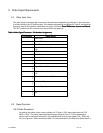
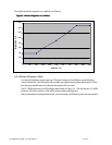
The DC Power Input Connector consists of two (2) positions wired numerically and supplied attached
to the LC1200R as a chassis mounted connector per definitions listed in Table 7.
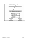
Table
Table Table
Table 7
77
7.
. .
. DC Power Input Connector
DC Power Input ConnectorDC Power Input Connector
DC Power Input Connector-
--
- Pin Assignments
Pin Assignments Pin Assignments
Pin Assignments
PIN NUMBER
PIN NUMBERPIN NUMBER
PIN NUMBER
SIGNAL NAME
SIGNAL NAMESIGNAL NAME
SIGNAL NAME
1 Positive Input Voltage (12V)
2 Return (GND)
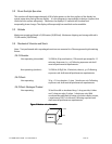
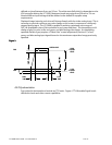
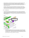
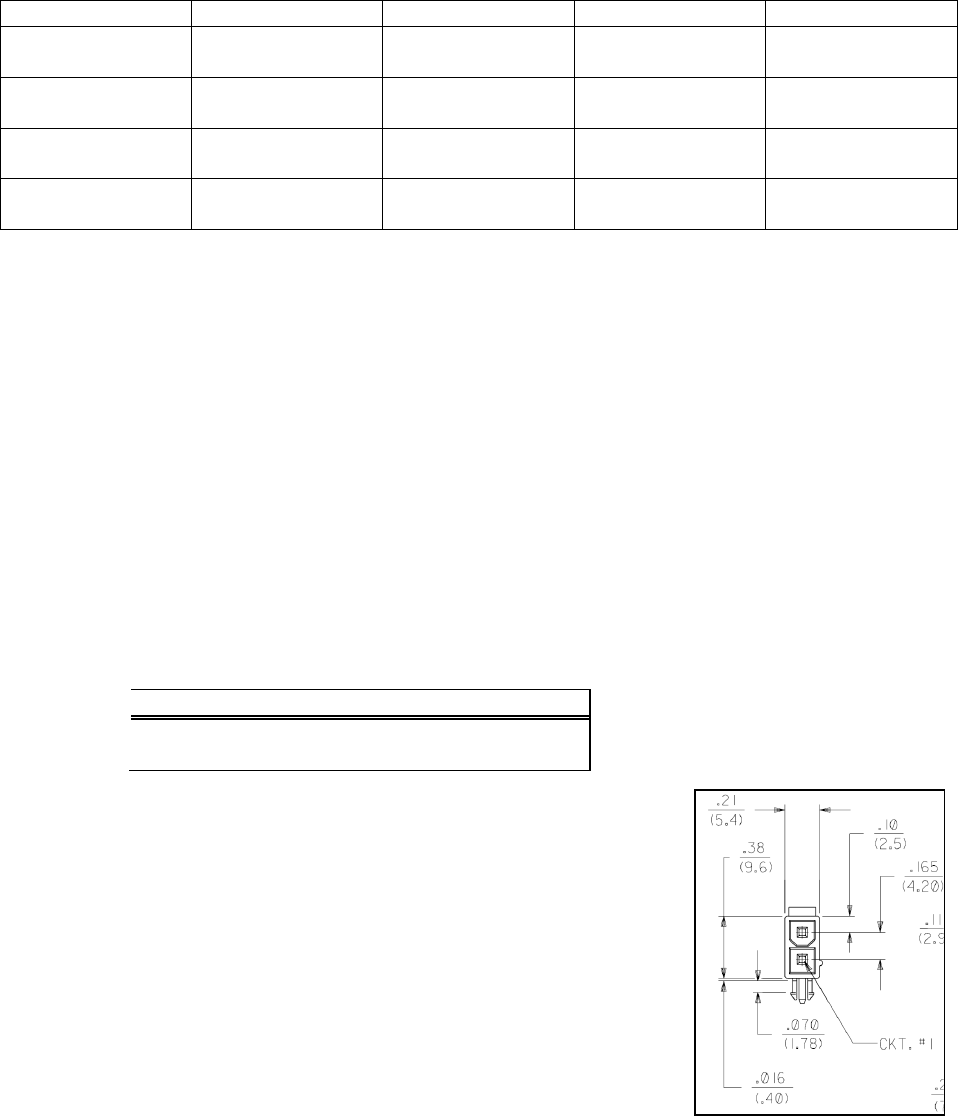
The DC Power Input Connector is a 2 pin Molex Mini Fit Jr. Pin
number assignments are defined in Table 7; shown below is the
physical layout as seen by the interface cable from the DC power
source.
Figure
Figure Figure
Figure 5
55
5
5.2 DC Input Voltage / Current
DC Input Voltage: 12
12 12
12 V DC
V DC V DC
V DC nominal, +
nominal, + nominal, +
nominal, +/
//
/-
--
-
.4
.4.4
.4
V DC
V DC V DC
V DC.
..
.
Over the specified input voltage range:
• No loss of image synchronization occurs.
• White display luminance level is within 10% of luminance at nominal input voltage.
• DC Input Current: 4.3 amp maximum current draw (12.4-vdc applied) steady state conditions.