


LC1200R User’s Guide
021-0183-00 Rev A 18 of 29
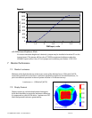
The Gain adjustment is to allow the full scale of the input video to be utilized. The direction of this
adjustment will reverse when a limit is reached. For example, it will adjust from maximum to
minimum, then reverse and go from minimum to maximum. The best way to make this adjustment is
with a continuous gray scale pattern on the display. A proper adjustment will give continuous
shading from black to white.
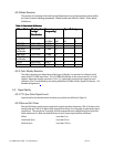
Auto Adjust: All four parameters (clock, Horizontal position, Vertical position, and gain) can be
adjusted automatically by pressing the Horz and DotClk+ button simultaneously. The LC1200R will
sense the incoming video and optimize its settings. For best results, display a pattern containing
white and black with some white pixels along all four edges while the auto adjust is performed.
6.2 User Adjustments
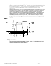
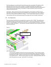
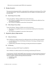
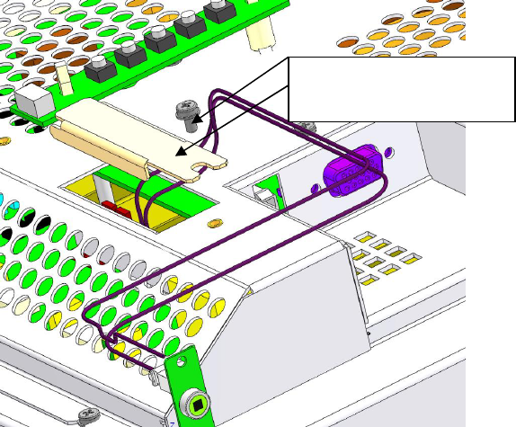
There are features that allow the user to adjust the properties of the LC1200R. These adjustments
will require access to the video board PCB and the inverter. Access to the Photodiode Connector
Section 2.5.3 and Dimming Control Connector Section 2.5.4 can be gained by removing 1 screw and a
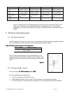
small access panel. See Figure 6. ESD precautions should be taken when removing this panel or the
back cover of the unit.
Figure 6:
6.2.1
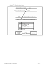
Flip and Mirror
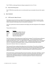
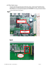
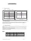
The unit has the capability to flip and/or mirror the video image. This can be done to allow
for the power and video connector to be located on the other side of the unit for flexibility in
mounting the LC1200R. Jumpers are located on the LCD Video Controller Board. See Figure
7 for jumper locations. Note the viewing angle in asymmetric. Rotating the display 180° will
affect the apparent view angle. See Section 7 for view angle.
Remove Screw and
Door