


LC1200R User’s Guide
021-0183-00 Rev A 7 of 29
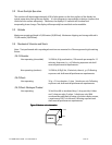
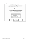
2.4 Cooling Fans
Four (4) thermostatically controlled cooling fans are provided to cool the rear of the display. The
thermostat is set to turn the fans on when the video board temperature reaches 30° C. If the display
is used in direct sunlight, airflow must be directed across the front of the display or the display LCD
fluid may reach its clearing point, then the LC1200R will become temporarily unreadable.
2.5 Connectors
There are four connectors supplied as an integral part of the LC1200R.
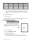
2.5.1
Video Signal Connector
The LC1200R unit includes a chassis mounted 15-pin female mini D-Shell connector (AMP
748390-5 or equivalent) with socket contacts at the rear of the LC1200R. It is shielded for
electromagnetic interference (EMI) purposes. Refer to Section 4.1 for electrical connections.
2.5.2
DC Power Input Connector
The DC power input connector is a chassis mounted 2-pin connector (Molex Mini Fit Jr
Header 5569 Molex p/n 39-30-0020) with pin contacts at the side of the LC1200R. The
connections are insulated to prevent accidental contact.
2.5.3
Photodiode Connector
A 3-pin connector, Molex p/n 22-03-5035, is provided on the inverter board. The connector
accepts the cable assembly provided with the product that attaches to the provided
photodiode board.
2.5.4
Dimming Control Connector
A 5-pin connector, Molex p/n 22-03-5055, provides an analog input that can override the
automatic photodiode dimming and allows the backlight to be shut down using an inhibit
input.
2.5.5
Button Board Connector
The Button board can be mounted remotely or removed for better access when mounted
into the larger system.
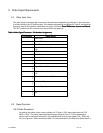
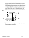
2.6 Interface Cables
The display is shipped with a remote photo-sensor and cable, removable button board, and 6 ft VGA
interface cable. No other interface cables are provided. An external power supply brick is available
for purchase from Planar Systems, Inc
.