4
Introduction
WARNING! The projector lamp can reach high temperatures expelling uncomfortably hot air
through the ventilation slots.
Note
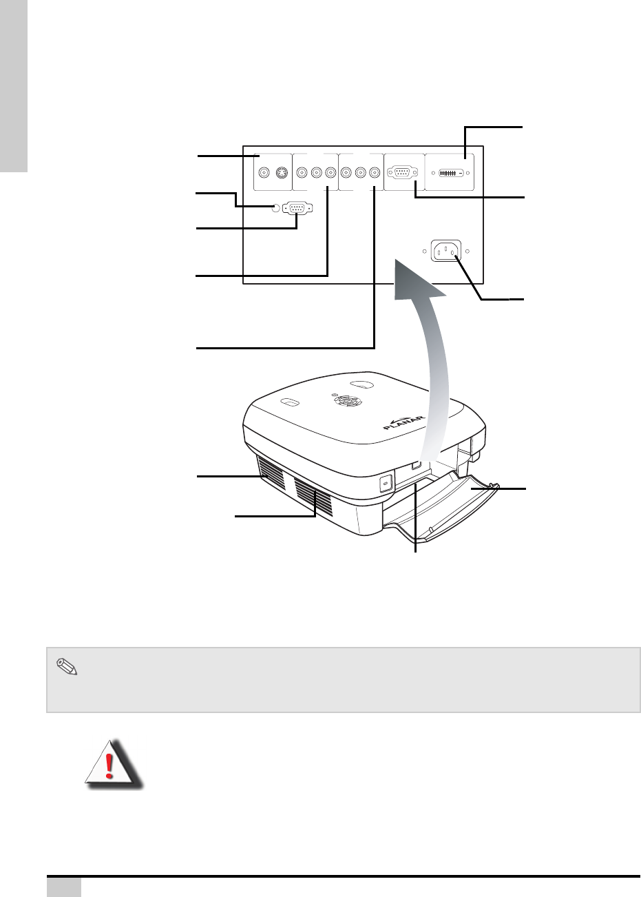
• Cables should run through the bottom clearance hole. The back cover allows for easy access to
terminals and is intended to conceal the cables after installation.
VIDEO S-VIDEO P
R
/C
R
P
B
/C
B
Y P
R
/C
R
P
B
/C
B
Y RGB-HD DVI-D
DVI-D RGB-HD
RS-232
AC110-240
AC110-240
12V
TRUGGER
12V
TRUGGER
RS-232
COMP1 COMP2
COMP1COMP2
Y
P
B
/C
B
P
R
/C
R
P
B
/C
B
P
R
/C
R
Y
S-VIDEO VIDEO
Source 1
: Component 1
Terminals for component
YPbPr/YCbCr.
Projector (Rear View)
Source 2: Component 2
Terminals for component and
YPbPr/YCbCr.
RS-232C terminal
Firmware upgrade/command
control.
Source 5: Video/S-Video
Terminal for connecting video
equipment with an S-video or
Composite Video terminal.
AC socket
Input: 100~240VAC
3.5A,50/60Hz
Intake vent
Source 3
: DVI
Terminal for computer
and RGB
signals.
Source 4
: PC
Terminal for Digital
Video Interface.
Cooling fan
Back Cover
Open the back
cover to access all
connectors.
12V Trigger
Terminal for screen controlling
Bottom
clearance hole


