


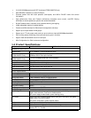
5
LED
Color Function
LNK/ACT
Green
Lit: indicate the link through that port is successfully established.
Blink: indicate that the switch is actively sending or receiving data over that port.
100
Orange
Lit: indicate that the port is operating at 100Mbps.
Off: indicate that the port is operating at 10Mbps.
PoE In-use
Green
Lit: indicate that the port is providing 48VDC to remote Powered Device
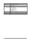
Per 10/100/1000Mbps port (FGSW-2620PVS only)
LED
Color Function
LNK/ACT
Green
Lit: indicate the link through that port is successfully established.
Blink: indicate that the switch is actively sending or receiving data over that port.
100/1000
Green / Orange
Orange: indicate that the port is operating at 1000Mbps.
Green: indicate that the port is operating at 100Mbps.
FDX/COL
Green
Lit: indicate that port is operating in full-duplex mode.
Off: indicate that port is operating in half-duplex mode.
Blink: if a collision is detected when the port is in half-Duplex mode.
"01#
The extension slots #25 and #26 of FGSW-2402PVS can be a 10/100Base-TX, 1000Base-T or 100Base-FX,
1000Base-SX/LX switching port as the extension module installed.
Please refer to the section 3.2.4 Port Configuration for the detailed installation and settings.
2!)#*+",-#.!)#* +/,-#
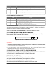
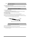
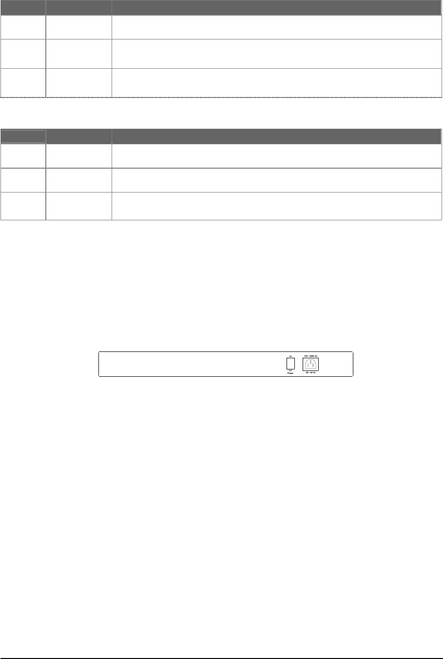
The rear panel of the Switch indicates an AC inlet power socket, which accepts input power from 100 to
240VAC, 50-60Hz. Figure 2-3 shows Rear panel of the Switch.
Figure 2-3 Rear Panel of FGSW-2402PVS/FGSW-2620PVS
Power Notice:
1. The device is a power-required device, it means, it will not work till it is powered. If your networks should
active all the time, please consider using UPS (Uninterrupted Power Supply) for your device. It will prevent
you from network data loss or network downtime.
2.
In some area, installing a surge suppression device may also help to protect your Switch from being
damaged by unregulated surge or current to the Switch or the power adapter.
!)#*+",-#.!)#* +/,-#
This part describes how to install your Web Smart Ethernet Switch and make connections to the Switch. Please
read the following topics and perform the procedures in the order being presented.
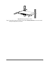
To install your Switch on a desktop or shelf, simply complete the following steps.
$
To install a Switch on a desktop or shelf, simply complete the following steps:
Step1: Attach the rubber feet to the recessed areas on the bottom of the Switch.
Step2: Place the Switch on a desktop or shelf near an AC power source.
Step3: Keep enough ventilation space between the Switch and the surrounding objects