


4
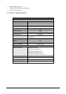
Per 1000Base-T port
LED Color Function
LNK/ACT Green
Lit: indicate the link through that port is successfully established.
Blink: indicate that the switch is actively sending or receiving data over that port.
SPEED Green/orange
Green: indicate that the port is operating at 1000Mbps.
Orange: indicate that the port is operating at 100Mbps.
Per SFP-Mini-GBIC port
LED Color Function
LNK/ACT Green
Lit: indicate the link through that port is successfully established.
Blink: indicate that the switch is actively sending or receiving data over that port.
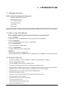
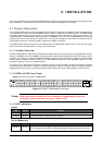
2.1.4 FGSW-4840S Rear Panel
The rear panel of the Switch indicates an AC inlet power socket, which accepts input power from 100 to 240VAC,
50-60Hz.
100~240V AC
50/60 Hz
Figure 2-2 Rear Panel of FGSW-4840S
Power Notice:
1. The device is a power-required device, it means, it will not work till it is powered. If your networks should active all the
time, please consider using UPS (Uninterrupted Power Supply) for your device. It will prevent you from network data loss
or network downtime.
2. In some area, installing a surge suppression device may also help to protect your switch from being damaged by
unregulated surge or current to the Switch or the power adapter.
2.2 Installing a FGSW-4840S
This section describes how to install your FGSW-4840S Web Smart Gigabit Ethernet Switch and make connections to the
switch. Please read the following topics and perform the procedures in the order being presented. PLANET FGSW-4840S
Web Smart Gigabit Ethernet Switch do not need software configuration. To install your FGSW-4840S on a desktop or shelf,
simply complete the following steps.
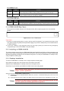
2.2.1 Desktop Installation
To install an FGSW-4840S on a desktop or shelf, simply complete the following steps:
Step1: Attach the rubber feet to the recessed areas on the bottom of the switch.
Step2: Place the FGSW-4840S on a desktop or shelf near an AC power source.
Step3: Keep enough ventilation space between the Switch and the surrounding objects.
Note:
When choosing a location, please keep in mind the environmental restrictions discussed in
Chapter 1, Section 4, Specification.
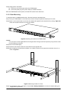
Step4: Connect your FGSW-4840S to network devices.
A. Connect one end of a standard network cable to the 10/100 or 10/100/1000 RJ-45 ports on the front of the
FGSW-4840S
B. Connect the other end of the cable to the network devices such as printer servers, workstations or routers…etc.
Note:
Connection to the Switch requires UTP Category 5 network cabling with RJ-45 tips. For more
information, please see the Cabling Specification in Appendix A.