19
Operating Controls
Start/Stop
Power Indicator Light – The start switch has a
power indicator lamp which is on whenever
there is power connected to the shaper, not
just when the shaper is running. Do not assume
that no light means there is no power to the
machine. If the bulb is bad, there will be no
indication. Always check before use.
Do not rely that no light
means no power to the machine. Always
check for power first. Failure to comply may
cause serious injury!
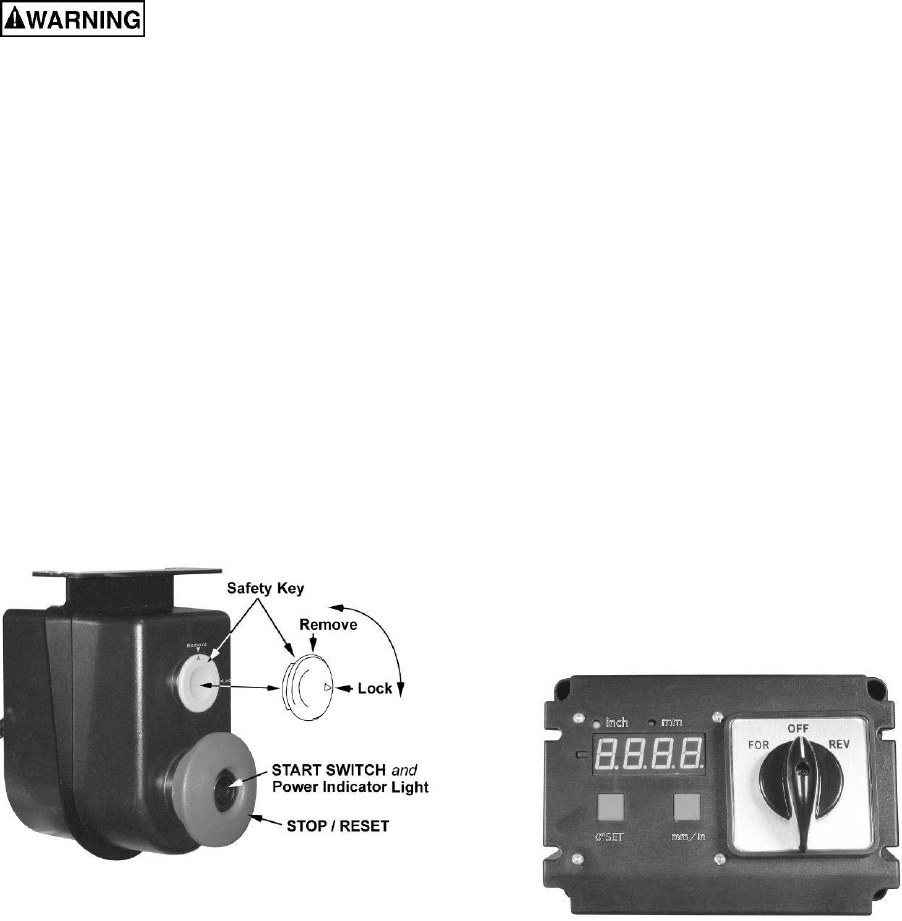
Referring to Figure 20:
Start – Press the green start switch (see Note).
When power is connected to the machine, the
green light is always on regardless of whether
the shaper is running or not.
Note: In addition, the switch on the digital
readout must be set to forward (or reverse) and
the cabinet door must be closed.
Stop – Press the red switch to stop.
Reset – In the event that the shaper stops
without pressing the stop button, as the result of
a tripped fuse or circuit breaker, etc.:
1. Press red button to reset
2. Press the green button to restart the
machine.
Figure 20
Safety Key
The start/stop switch on the Model 2700 comes
equipped with a magnetic safety key. When in
place on the switch as shown in Figure 20 the
magnetic safety key trips a relay which will allow
the machine to start and stop when the
respective switches are pressed. Being
magnetic, the lock can be removed to make the
machine inoperable and can be hidden for safe
storage by attaching it underneath the rail or
another magnetic surface.
When using the shaper, place the key on the
switch cover lining up the arrow on the key with
the REMOVE arrow on the cover. Then rotate
the key so the arrow lines up with the LOCK
arrow. This will prevent the safety key from
coming loose from vibration when the machine
is in use.
Digital Readout
The digital readout (Figure 21) is used for
making incremental spindle height adjustments
where applicable, if multiple shaping/cutting
passes are to be performed on a given work-
piece.
Set the digital readout as follows:
1. Set the desired spindle height for the
workpiece to be cut.
2. Supply power to the machine so the digital
display is lit.
3. Select inch or mm by momentarily
depressing the button on the right.
4. Press the 0" SET button for approximately
two seconds.
The digital display resets to zero, which is your
reference point. When the spindle is raised or
lowered (front handwheel), the change is relative
to this reference.
If this feature is used, the display should be
reset to zero for each new cutting operation.
Figure 21
