SN0051408-00 C 10
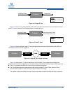
Figure 4-1. Single E_Port
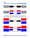
Figure 4-2 shows how a Fibre Channel switch with more than one online E_Port must determine from
which E_Port an incoming Fibre Channel frame is routed (sent) out.
Figure 4-2. Dual E_Ports
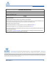
Figure 4-3 shows a simple, single E_Port topology between two non-high availability (HA) SANs. All
FCIP traffic flows across this single link.
Figure 4-3. Single E_Port, Single Switches
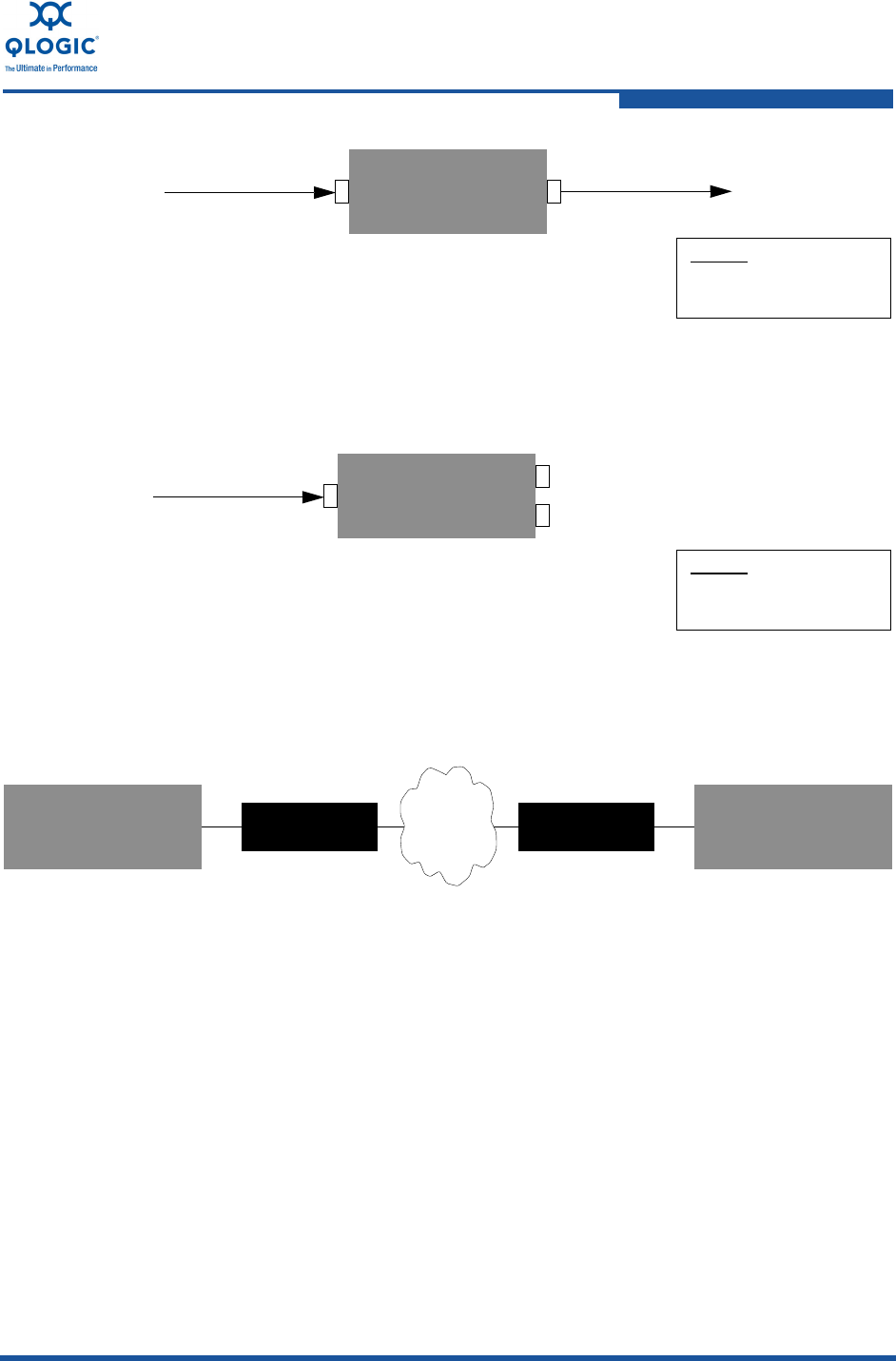
Figure 4-4 shows dual E_Ports connecting two non-HA SANs. This configuration provides Fibre
Channel link level failover protection and can yield additional bandwidth if the following conditions are met:
The IP link between the iSR6142s can utilize the additional throughput.
The Fibre Channel switches load balance traffic across multiple E_Ports. Check with your Fibre
Channel switch vendor to verify this (most require additional licensing).
The addition of a second iSR6142 at each site provides both link level and iSR6142 failure protection.
FC Switch
Incoming Frame
21
Frame Sent
1 F_Port/FL_Port/N_Port
Legend
2 E_Port
FC Switch
Incoming Frame
2
1
1 F_Port/FL_Port/N_Port
Legend
2 E_Port
2
Fibre Channel Switch Now
Decides Which Port to Use
FC SwitchFC Switch
iSR6142 iSR6142WAN
FC FC
FC SwitchFC Switch FC SwitchFC Switch


