SN0051408-00 C 9
d. Verify the router-to-switch Fibre Channel connectivity:
On the Fibre Channel switches, the port connected to the router should appear as an E_Port.
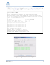
On the routers, verify the connectivity using the CLI or iSCSI/FC Router Manager. When using
the GUI, remember to refresh the display.
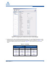
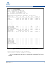
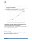
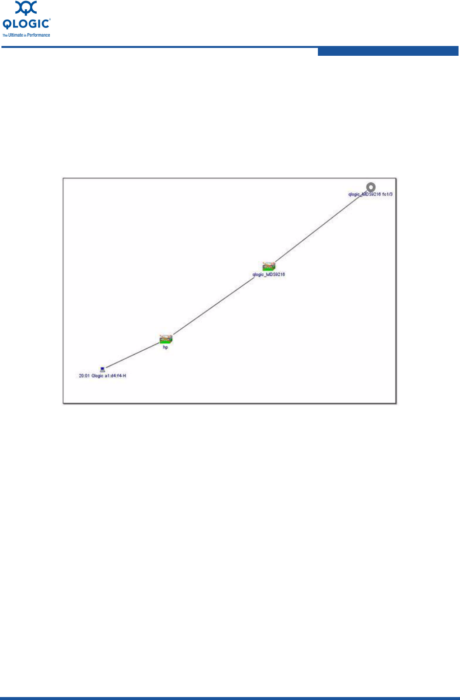
The Fibre Channel switches should now show an ISL between each other. Most Fibre Channel
switch user interfaces have a topology display that shows the ISL (see Figure 3-6).
Figure 3-6. Fibre Channel Switch Topology with ISL
9. Fibre Channel switch zoning is affected when the Fibre Channel switches are linked by an ISL
(merged). Review your switch zoning and correct any inconsistencies.
The purpose of the FCIP route example in this applications note is to provide data replication
between the two storage arrays. Therefore, after the FCIP route (ISL) is established, you must zone
together the storage array ports used for data replication.
You have successfully completed installation of the iSR6142 and configuration of an FCIP route.
4
Advanced Topologies
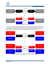
The drawings in this section illustrate several more advanced topologies for multiple routes.
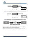
Figure 4-1 shows how a Fibre Channel switch with a single E_Port can simply route all Fibre Channel
frames bound for any non-local device out of the known E_Port.


