6
Step 3. Mount the Router
Mount the router in the rack using the rack mount kit with instructions provided.
Step 4. Install the SFPs
An SFP transceiver is required for each router port that will be connected to a Fibre Channel device or switch. SFPs are
included in the package. If you prefer using different SFP transceivers from the ones provided, purchase one of the
following QLogic recommended transceivers:
❑ Finisar
❑ JDS Uniphase
To install an SFP transceiver, insert the transceiver into the router port and press gently until it snaps in place. The
transceiver will fit only one way. If the transceiver does not install under gentle pressure, flip it over and try again.
Step 5. Apply Power to the iSR6250 Router
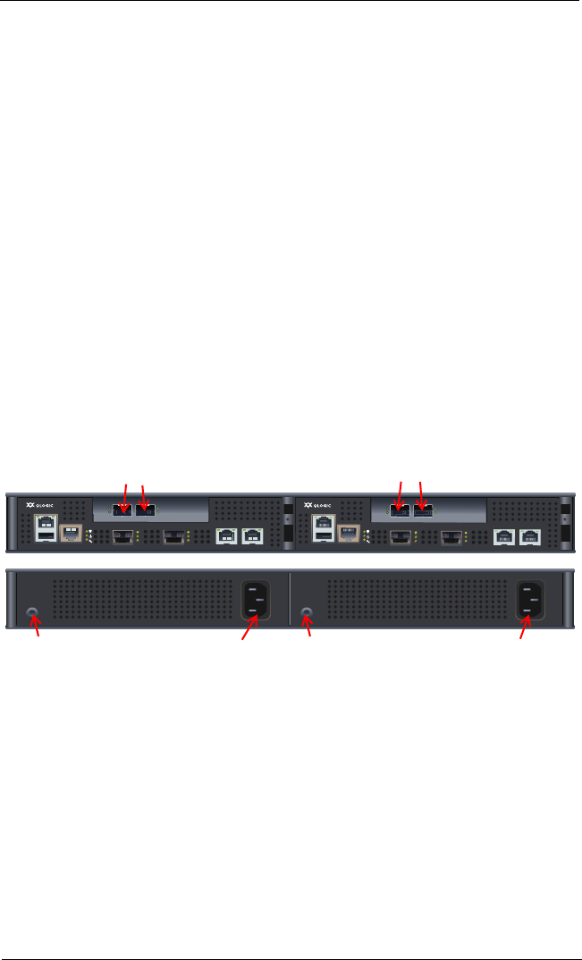
The iSR6250 router chassis contains two router blades, along with a power cooling module (PCM) for each blade. Each
chassis blade provides LEDs and connectors that face the front of the chassis. Each PCM provides a power connector,
as well as an LED (see Figure 3).
Figure 3. iSR6250 Router Chassis — Front and Back Plates
1. Attach the AC power cord to the power connector, located on the backside of the PCM connected directly
behind the router blade.
2. Connect the opposite end of the power cord to the wall outlet or power strip.
3. Check the PCM power LED to make sure the PCM is operational (green = OK, yellow = no AC power).
Figure 4 shows the location of the ports and LEDs on one of the blades contained within the iSR6250 unit
that are referenced in the following instructions.
MGMT IOIOI
FC1 FC2
MGMT IOIOI
FC1 FC2
10GbE1 iSR6250
Intelligent Storage Router
10GbE2
10GbE1 iSR6250
Intelligent Storage Router
10GbE2
10Gb iSCSI Ports
Front Plate iSR6250 Blade 1 Front Plate iSR6250 Blade 2
10Gb iSCSI Ports
Power Connector
Back Plate PCM for Blade 2
PCM Status LED Power Connector
Back Plate PCM for Blade 1
PCM Status LED
