Installing internal tape drives Reviewing Drive Default Settings
20
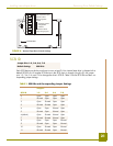
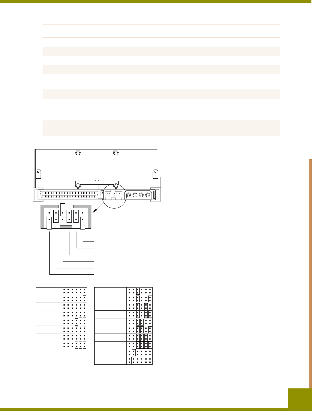
FIGURE 3. Internal Tape Drive Jumper Settings
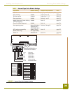
TABLE 2. Internal Tape Drive Default Settings
Parameter Default Setting Jumper Pins/Switches See...
SCSI ID 6 Jumper pins 1–2, 3–4, 5–6, 7–8 page 21
Parity checking Enabled Jumper pins 9–10 page 22
Terminator power Disabled Jumper pins 11–12 page 22
Data compression Enabled Switches 1 and 2 page 23
Media Recognition System checking
(DDS-4 drives only)
Enabled Switch 3 page 23
Power-On Self-Test diagnostic Enabled Switch 4 page 24
Host operating system Microsoft Windows
98/Me/XP/NT/
2000/2003 Server
Switches 5 through 8 page 24
SCSI interface compatibility
(DDS-4 drives only)
Wide SCSI (LVD
and single ended)
Switch 9 page 25
Vendor ID SEAGATE DAT Switch 10 page 25
SCSI ID=0
SCSI ID=1
SCSI ID=2
SCSI ID=3
SCSI ID=4
SCSI ID=5
SCSI ID=6
SCSI ID=7
SCSI ID=8
SCSI ID=9
SCSI ID=10
SCSI ID=11
SCSI ID=12
SCSI ID=13
SCSI ID=14
SCSI ID=15
Parity enable
Term. power
Default jumper settings shown
(SCSI ID 6, parity checking enabled,
and termination power disabled)
Pins: Function:
1-2 SCSI ID bit 0
3-4 SCSI ID bit 1
5-6 SCSI ID bit 2
7-8 SCSI ID bit 3
9-10 Parity checking
11-12 Termination Power


