


AirborneDirect™ Users Guide Quatech, Inc.
100-8510-110 2/21/2011 29
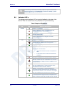
PCB Embedded – This approach embeds an antenna design into the host PCB.
This approach is very common with add-in WiFi cards (CF, PCMCIA, SDIO, etc.)
as it requires no external connections and is the cheapest production approach.
The lower production cost requires significant development cost and lack of
performance and flexibility.
Chip – The integration of a chip antenna is simple and requires a relatively small
footprint on the host system, however, it does suffer from the same limitations of
flexibility and performance seen with the PCB embedded approach. There are
relatively large numbers of suppliers of this type of antenna; there is also a range
of configuration and performance options.
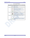
Flying Lead – This approach is similar to the flying lead solution for external
antennas. The difference is that the form factors are smaller and provide a range
of chassis and board mounting options, all for internal use. This approach suffers
less from the performance and flexibility limitations of the other approaches,
since the location of the antenna it not determined by the host PCB design. The
assembly of a system using this approach maybe slightly more complex since
the antenna is not necessarily mounted on the host PCBA.
8.5 Antenna Location
The importance of this design choice cannot be over stressed. It can in fact be
the determining factor between success and failure of the WiFi implementation.
There are several factors that need to be considered when determining location:
Distance of Antenna from radio
Location of host system
Proximity to RF blocking or absorbing materials
Proximity to potential noise or interference
Position relative to infrastructure (Access Points or Laptops)
Orientation of host system relative to infrastructure
Is it known
Is it static
To minimize the impact of the factors above the following things need to be
considered during the development process:
Minimize the distance between the radio and the location of the antenna. The
coaxial cable between the two impacts the Transmit Power and Receive
Sensitivity negatively. Quatech recommends using 1.32-1.37mm outer
diameter U.FL coaxial cables.
Minimize the locations where metal surfaces come into contact or are close
to the location of the antenna.
Avoid locations where RF noise, close to or over lapping the ISM bands, may
occur. This would include microwave ovens and wireless telephone systems
in the 2.4GHz and 5.0GHz frequency range.
Mount the antenna as high on the equipment as possible.