


AirborneDirect™ Users Guide Quatech, Inc.
100-8510-110 2/21/2011 7
Figures
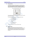
Figure 1 - Enterprise AirborneDirect™ Device ................................................................................................................. 13
Figure 2 - Industrial AirborneDirect™ Device ................................................................................................................... 14
Figure 3 - Heavy Duty AirborneDirect™ Device ............................................................................................................... 14
Figure 4 - ABDG-SE/ET-DP5XX Block Diagram .............................................................................................................. 16
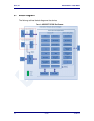
Figure 5 - ABDG-ET/SE-IN5XXX Block Diagram ............................................................................................................. 17
Figure 6 - DE-9 (DB-9) Connector Pin-out........................................................................................................................ 18
Figure 7 - Ethernet Jack Pin Out ...................................................................................................................................... 19
Figure 8- Interface Selection Jumpers.............................................................................................................................. 21
Figure 9 - Website Login .................................................................................................................................................. 44
Figure 10 - Default Home Page ....................................................................................................................................... 45
Figure 11 - Website Navigation Bar ................................................................................................................................. 45
Figure 12- Feature Links .................................................................................................................................................. 46
Figure 13 - Airborne Web Page ....................................................................................................................................... 47
Figure 14 - upload Certificate Web page .......................................................................................................................... 48
Figure 15 - Upload Configuration Web Page .................................................................................................................... 49
Figure 16 - Firmware Update Page .................................................................................................................................. 50
Figure 17 - Firmware Update in Progress ........................................................................................................................ 51
Figure 18 - Firmware Update Complete ........................................................................................................................... 51
Figure 19 - Express Setup Page ...................................................................................................................................... 53
Figure 20 - Ethernet Bridge Functionality ......................................................................................................................... 81
Figure 21 - Airborne Ethernet Bridge IP Configuration ..................................................................................................... 83
Tables
Table 1 – Serial Port Pin Definition .................................................................................................................................. 18
Table 2 - Serial Ports by Product Class ............................................................................................................................ 19
Table 3 - Ethernet Connector Pin Out .............................................................................................................................. 19
Table 4 - Connector Description....................................................................................................................................... 20
Table 5 - OEM Reset Procedure ...................................................................................................................................... 21
Table 6 - Enterprise LED Indicators ................................................................................................................................. 22
Table 7 - Industrial LED Indicators ................................................................................................................................... 23
Table 8- Absolute Maximum Values
1
............................................................................................................................... 24
Table 9 - RF Characteristics – 802.11b/g ......................................................................................................................... 24
Table 10 - Supported Data Rates by Band ....................................................................................................................... 25
Table 11 - Operating Channels ........................................................................................................................................ 25
Table 12 - Radio Typical Performance Range .................................................................................................................. 26
Table 13 - Embedded Antenna Options ........................................................................................................................... 28
Table 14 - SE-IN5XXX Accessing the Web Interface ....................................................................................................... 35
Table 15 - UART Authentication....................................................................................................................................... 38
Table 16 - UART SSID & Authentication .......................................................................................................................... 39
Table 17 - UART Determine Module's IP Address ........................................................................................................... 39
Table 18 - ET-DP5XX/IN5XXX Accessing the Web Interface ........................................................................................... 41
Table 19 - Navigation Bar Items ....................................................................................................................................... 45
Table 20 - Uploading Certificates ..................................................................................................................................... 48
Table 21 - Uploading Configurations ................................................................................................................................ 49
Table 22 - Updating Firmware .......................................................................................................................................... 51
Table 23 - Express Page Setup ....................................................................................................................................... 53
Table 24 - Configuring Wireless Interface - Infrastructure ................................................................................................ 56
Table 25 - Configuring Wireless Interface - AdHoc ........................................................................................................... 57
Table 26 - Configuring for WEP Security .......................................................................................................................... 58
Table 27 - Configuring for WPA Security .......................................................................................................................... 59
Table 28 - Configuring for WPA2 Security ........................................................................................................................ 60
Table 29 - Configuring for PEAP Security ........................................................................................................................ 61
Table 30 - Configuring DHCP - WLAN ............................................................................................................................. 63
Table 31 - Configuring DHCP - Ethernet .......................................................................................................................... 64
Table 32 - Configuring Static IP - WLAN .......................................................................................................................... 65
Table 33 - Configuring Static IP - Ethernet ....................................................................................................................... 66
Table 34 – Configure Data Tunnel on Telnet Port ............................................................................................................ 68
Table 35 - Data Tunnel using Telnet Port ......................................................................................................................... 69
Table 36 – Configure Data Tunnel on Serial Port 1 Tunnel Port (TCP) ............................................................................. 70
Table 37 - Data Tunnel using Tunnel Port on Serial Port 1............................................................................................... 70
Table 38 – Configure Data Tunnel on Serial Port 2 Tunnel Port (TCP) ............................................................................. 71
Table 39 - Data Tunnel using Tunnel Port on Serial Port 2............................................................................................... 72
Table 40 - Configure Serial Port 1 as TCP Client ............................................................................................................. 72
Table 41 - Configure Serial Port 2 as TCP Client ............................................................................................................. 73
Table 42 - Install VCOM ................................................................................................................................................... 75
Table 43 - Cable Replacement - Slave Configuration ....................................................................................................... 78