


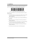
4. Addressing Ports
4.1 Setting the address
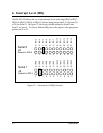
The base address of each port of the DS-200/300 is set using two DIP switch
packs. When setting the address selection switches, a switch in the "ON" position
specifies that the corresponding address line must be a logic 0 for the port to be
selected. Similarly, a switch in the "OFF" position forces the corresponding
address line to be a logic 1 for the port to be selected.
A full sixteen bit address decode is implemented to reduce the chance of address
conflicts with other adapters in the system. Each serial port on the DS-200/300
uses 8 consecutive I/O locations. The two ports reside in their own independent
block of I/O space in eight byte increments.
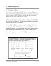
Switches SW1 and SW2 select address lines A15 through A3 for Serial 0 and
switches SW3 and SW4 select address lines A15 through A3 for Serial 1. The
remaining address lines (A2, A1 and A0) are used by the UART to select the
register being accessed. The sixth position on SW2 is used to enable or disable
Serial 0 and the sixth position on SW4 is used to enable or disable Serial 1.
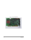
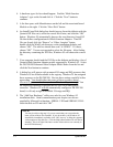
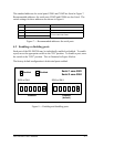
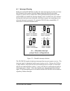
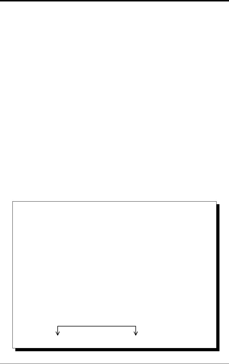
Figure 5 shows how the switches on the DS-200/300 represent the address values
for serial ports. This figure can be used to explain the examples shown in Figure
6.
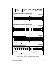
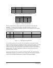
two, and one, hence the maximum value of 8+4+2+1 = 15.
A serial port's address is a 16-bit quantity that is most often expressed
in four hexadecimal (base 16) digits. A hex digit can hold a value from 0 to
15 (decimal), and is made up of four binary bits given weights of eight, four,
A possible serial port address is 5220 hex. The example below shows
how the hex digits are broken down into binary bits.
Bit weight
Binary bits
Sum of bits
Hex digits
2
2
0
5
8 4 2 1 8 4 2 1 8 4 2 1 8 4 2 1
0+4+0+1 0+0+2+0 0+0+2+0 0+0+0+0
0 1 0 1 0 0 1 0 0 0 1 0 0 0 0 0
0 1 0 1 0 0 1 0 0 0 1 0 0 0 0 0
These address bits are set by the switches.
All other bits are considered to be zero.
Figure 5 --- Examination of a serial port base address
DS-200/300 User's Manual 4-1