


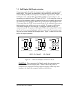
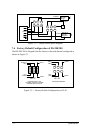

7. Output Configuration
The DS-200/300 provides four differential communication signals per channel.
The two output signals are Transmit Data (TxD) and Auxiliary Output
(AUXOUT). The two input signals are Receive Data (RxD) and Auxiliary Input
(AUXIN). A ground signal is also provided.
The DS-200/300 allows the user to select whether handshaking signals or clock
signals are transmitted over the auxiliary lines. The available input signals for
AUXIN are Clear To Send (CTS) and the Receive Clock (RCLK). The available
output signals for AUXOUT are Request To Send (RTS), the Transmit Clock
(XCLK), and the AUXIN signal (for loopback). Configuration is done using
jumpers J5 and J7.
Either half-duplex or full-duplex operation can be selected for each
communications channel. If half-duplex operation is selected, one of the UART's
signals (either DTR or RTS) is used to enable the transmitter drivers (TXEN).
The inverse of the transmitter enable (/TXEN) is used to enable the receiver
drivers (RXEN). This insures that the driver and the receiver are not enabled at
the same time. Configuration is done using jumpers J6 and J8.
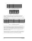
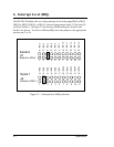
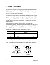
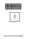
XSerial 1J8
XSerial 1J7
XSerial 0J6
XSerial 0J5
AUX SIGNALFULL/HALF
DUPLEX
CHANNELJUMPER
Figure 15 --- Jumper/Channel/Function correspondence
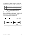
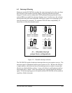
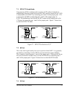
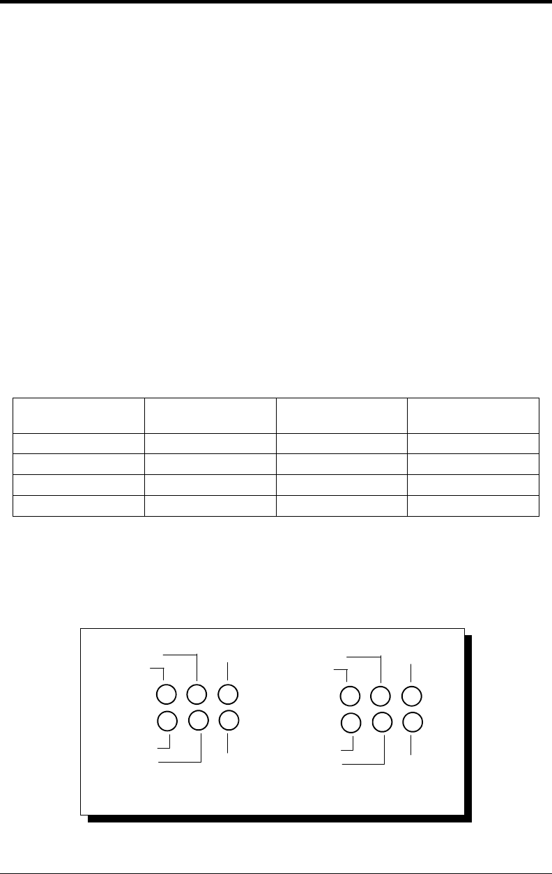
Figure 16 illustrates how connecting adjacent pins on the jumper pack routes
communication signals.
J5, J7
AUXOUT
RTS
AUXIN
CTS
XCLK
RCLK
6
3
2
5
1
4
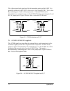
J6, J8
TXEN
/TXEN
RXEN
6
3
2
5
1
4
TXEN
DTR
RTS
Figure 16 --- Pinout of jumpers J5-J8
7-1 Quatech Inc.