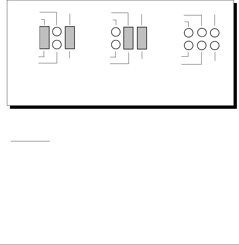
7.5 Half Duplex/Full Duplex selection
Using jumper packs J6 and J8, the channels can be configured to operate in half
duplex mode. This causes the transmitters to be controlled by either the Data
Terminal Ready (DTR) or the Request to Send (RTS) output from the UART. In
half duplex mode, if the UART signal (DTR or RTS) is asserted (logic 1), the
transmitters are enabled for both TxD and AUXOUT. At the same time, since the
inverse of the transmitter enable is connected to the receiver enable, the receivers
are disabled and the signal lines RXD and AUXIN enter a high-impedence state.
If the signal from the UART is not asserted (logic 0), the transmitter lines enter a
high-impedance state and the receivers are enabled. To operate in half-duplex
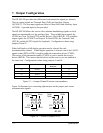
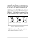
DTR mode, configure J6/J8 so that pin 1 is connected to pin 4 and pin 3 is
connected to pin 6. To operate in half-duplex RTS mode, configure J6/J8 so that
pins 2 and 5 are connected and pins 3 and 6 are connected. The transmitters and
receivers are always enabled in full duplex mode. Figure 21 shows how to select
half or full duplex operation.
Half-Duplex(DTR) Operation
Full-Duplex Operation
Half-Duplex(RTS) Operation
TXEN
TXEN
DTR
RTS
2
RXEN
/TXEN
5
TXEN
TXEN
DTR
RTS
RXEN
/TXEN
1
4
1
3
2
TXEN
/TXEN
RXEN
45
6
TXEN
DTR
RTS
J6/J8 J6 = Serial0 J8 = Serial1
Figure 21 --- Half or Full Duplex selection on J6, J8
WARNING: When operating in half duplex mode, the transmitters must
be disabled before receiving any data. Failure to do so may result in
multiple active output drivers being connected together, which may cause
damage to the board, the computer, and the external device.
DS-200/300 User's Manual 7-4


