


5. Data Rate Multiplier
A standard RS-422/485 serial port operates at a clock speed of 1.8432 MHz. In
order to achieve higher data rates, the DS-200/300 Enhanced Serial Adapter can
operate at two times, four times (16750 UART only), or even eight times (16750
UART only) this standard clock speed. The user can set this speed, known as the
data rate multiplier, in two different ways: by modifying hardware jumper settings
or by writing to a DS-200/300 register known as the Options Register.
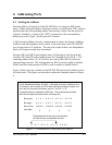
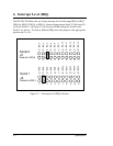
5.1 Data Rate Multiplier Jumper Block
The data rate multiplier jumper block (J9) is used to set the data rate multiplier if
software is not available to do so. This jumper block contains five positions
(three positions with the 16550 UARTs): X8 (16750 UART only), X4 (16750
UART only), X2, SW, and SP. Placing a jumper in the X2, X4, or X8 positions
sets the data rate multiplier accordingly. Placing a jumper in the SW position tells
the board to fetch its data rate multiplier from the Options Register. The SP
jumper position determines access to two special registers on the DS-200/300: the
Interrupt Status Register (ISR) and the Options Register (OR). Virtually no
commercially available software makes use of the Scratchpad Register (SCR) on
the UART at [base address+7]. By co-locating the new DS-200/300 registers at
this address, the use of additional I/O memory locations has been avoided. If the
SP jumper is installed, the SCR of the UART will be accessed at [base
address+7], as in a standard serial port. However, if the SP jumper is removed,
then either the ISR (see Section 6) or the OR will be accessed at [base address+7].
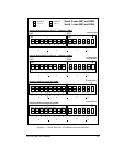
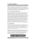
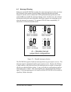
5.2 Options Register
The DS-200/300 is equipped with an Options Register which has two functions: a
two-bit rate register which allows software to set the data rate multiplier and a
two-bit ID register which allows software to identify the DS-200/300. The
register is located at [base address+7], and requires that the SP jumper be removed
and the DLAB bit in the Line Control Register (LCR) of the UART be set to 1.
See Figure 9 for the structure of the OR.
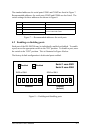
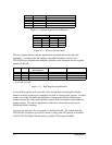
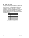
The ID register provides a means for software applications to identify the board as
a DS-200/300. It does this by performing logic on the bits written to these
locations so that the values read out of these locations will not necessarily be the
values that were written to these locations. When performing a write-read
operation to the ID register, the software can identify a DS-200/300 board by
recognizing the pattern read back from the ID bits (seeFigure 10).
ID register bit 0ID06
ID register bit 1ID17
DESCRIPTIONNAMEBIT
DS-200/300 User's Manual 5-1