


Chapter 2 Installation MBE Family Installation and Operation Manual
2-2 Installation and Setup
2.3 Package Contents
The following items are included in the MBE product packaging:
• One MBE standalone unit
• Control cable with RJ-45 connector – CBL-RJ45/D9/F/6FT
• AC power cord
• MBE Family Installation and Operation Manual
• LAN RANger Series Configuration Guide.
2.4 Equipment Needed
The following equipment is required to install the MBE:
• ASCII terminal or PC terminal emulator
• CBL-RJ45/D9/F/6FT control cable with RJ-45 connector (supplied with the
device) for connection to the configuration terminal.
2.5 Installation and Setup
MBE is a standalone unit intended for tabletop or bench installation. It is delivered
completely assembled. No provision is made for bolting the unit on the tabletop.
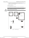
To install the MBE unit:
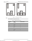
1. Determine the required configuration of MBE and set the internal jumpers
accordingly.
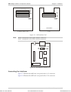
2. Connect the line (see Connecting the Interfaces below).
3. Connect the LAN (see Connecting the LAN below).
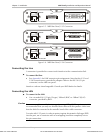
4. Connect power to the unit (see Connecting the Power below).
Access to the inside of the equipment is permitted only to authorized and
qualified personnel.
To avoid accidental electric shock, always disconnect the interface cables and
power cord before removing the unit from its casing.
Any adjustment, maintenance or repair of the opened instrument under
voltage must be avoided as much as possible, and when inevitable, should be
carried out only by a skilled technician who is aware of the hazards involved.
Warning
Order from: Cutter Networks
Ph:727-398-5252/Fax:727-397-9610
www.bestdatasource.com