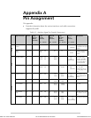
Appendix A Pin Assignment MBE Family Installation and Operation Manual
A-4
1
2
14
3
16
17
9
24
11
15
12
4
5
6
7
8
20
A
P
S
R
T
V
X
U
W
Y
AA (a)
C
D
E
B
F
H
Shield
V.35/ DB-25 V.35/ 34-pin
RTS
CTS
DCE Ready
Gnd
DCD
DTE Ready
Tx
Rx
R Clk
E Clk
T Clk
Tx
Rx
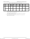
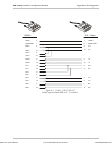
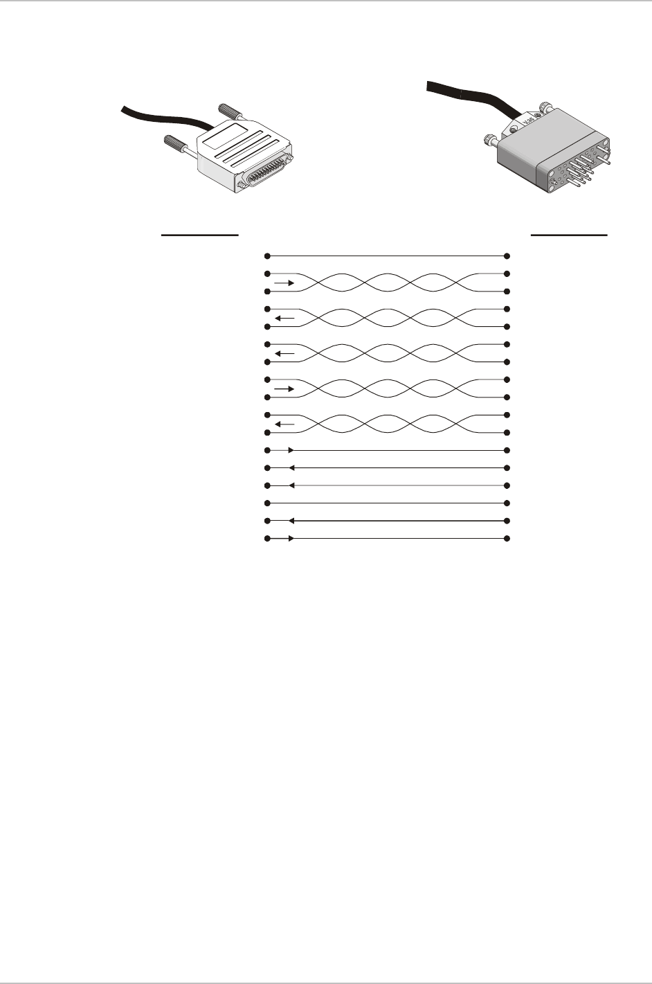
Figure A-2. Cable – CBL-530/V.35/F
Cable supplied with MBE10-1D, 8D for V.35 interface
Order from: Cutter Networks
Ph:727-398-5252/Fax:727-397-9610
www.bestdatasource.com


