


FCD-IPM Installation and Operation Manual Chapter 1 Introduction
Functional Description 1-5
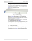
1.2 Physical Description
FCD-IPM units are delivered completely assembled. The units are designed for
desktop installation, or to be mounted in a 19-inch rack. Installation procedures
for FCD-IPM models and respective versions are provided in Chapter 2.
Figure 1-3 shows a 3-D diagram of FCD-IPM.
Figure 1-3. FCD-IPM General View
Controls and indicators of the various versions of FCD-IPM and their functions are
described in Chapter 3. The LED indicators on the front panel indicate the
operating status of FCD-IPM. Various indicators display status of user’s data port,
status of data activity in user’s data connector, and alert conditions. For a
description of the front panel, refer to Chapter 3.
The power and interface connectors are located on the rear panel of FCD-IPM.
For a description of the rear panel, refer to Chapter 2.
The internal jumpers of FCD-IPM are set according to options ordered. The only
jumper that you may need to set is the BAL/UNBAL jumper. The factory setting for
this jumper is BAL. For more information about setting jumpers, refer to Chapter 2.
1.3 Functional Description
This section describes the main and sublink characteristics, the data and voice
channel interfaces, timing considerations, time slot handling, integrated IP router
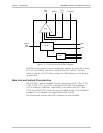
and management of FCD-IPM. Figure 1-4 shows a functional block diagram for
FCD-IPM.