


FCD-IPM Installation and Operation Manual Chapter 3 Operation
Connecting to the ASCII Terminal 3-5
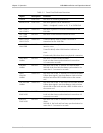
Fault Indications
If a fault occurs, the following alarm indicators light up, and data transfer may be
interrupted:
• LAN ERR indicator lights when LAN interface indicates an error
• LINK ERR indicator lights when LINK interface indicates an error
• RED ALARM indicator lights when T1 interface detects red alarm
• YELLOW ALARM indicator lights when T1 interface detects yellow alarm
• LOC SYNC LOSS indicator lights when the E1 interface detects local sync loss
• REM SYNC LOSS indicator lights when the E1 interface detects remote sync
loss.
To obtain additional information, observe the state of the other indicators and
then refer to Chapter 6 for troubleshooting information:
Turning Off
Set the FCD-IPM power switch, on the rear panel of the unit, to OFF.
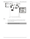
3.4 Connecting to the ASCII Terminal
FCD-IPM features a setup program that is invoked and run from an ASCII terminal
or a PC emulator. The terminal/terminal emulator is connected to the RJ-45
CONTROL port on the FCD-IPM front panel (see Figure 3-2).
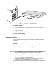
Connecting the Terminal Emulator
To connect the terminal emulator:
1. Attach the cable to the RS-232 port on the PC.
2. Attach the other end of the cable to the CONTROL port on the FCD-IPM front
panel.