


FCD-IPM Installation and Operation Manual Chapter 3 Operation
Operating Instructions 3-3
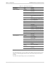
Table 3-1. Front Panel Indicator Functions (Cont.)
Object Description Function
LINK1 REM
SYNC LOSS
Red LED ON when E1 link is in remote sync loss alarm.
Remote sync loss signal is sent from Remote Unit to
inform the local unit that a sync loss exists at the remote
end.
SUB REM
SYNC LOSS
Red LED ON when one of the E1 sub link is in remote sync loss
alarm.
Remote sync loss signal is sent from Remote Unit to
inform the sub link of the local unit that a sync loss
exists at the remote end.
Rear Panel Indicators
Table 3-2. Rear Panel Indicator Functions
Object Description Function
LINK Green LED ON – LAN is connected to LAN1 or LAN2 connector or
to one of the Ethernet/Fast Ethernet switch ports.
100M Green LED ON – LAN speed is 100M
OFF – LAN speed is 10M
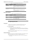
3.3 Operating Instructions
Turning On
In order for the unit to function, you must provide FCD-IPM with a setup
configuration. You configure the unit after the initial power-up stage.
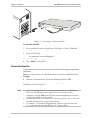
To turn on FCD-IPM:
• Set the power switch on the rear panel to ON.
FCD-IPM performs a self-test. All the FCD-IPM indicators should light up.
Confirm that all are operating. Following the test, all indicators except PWR
and READY turn off.
FCD-IPM is now ready for configuration. Refer to Chapter 4, for quick setup and
advanced configuration instructions.
Normal Indications
During normal operation the POWER indicator lights up, and the READY indicator
lights up when packets can be transferred. Additional indications are:
• The LAN DATA indicator lights when a packet is received or transmitted on
the LAN side