


Chapter 1 Introduction FCD-IPM Installation and Operation Manual
1-12 Technical Specifications
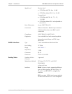
Signal Level
Receive level:
• FCD-IPM with CSU: 0 to –36 dB
• FCD-IPM without CSU: 0 to –10 dB
Transmit level:
• FCD-IPM with CSU: 0, -7.5, -15,
-22.5 dB
• FCD-IPM without CSU: soft adjustable at
0 to 655 ft.
Jitter Performance
As per AT&T TR-62411
Connectors
Balanced interface: RJ-48c 8-pin connector
Unbalanced interface: two BNC coaxial
connectors
Compliance
AT&T TR62411, ANSI T1.403
Diagnostics
User available local and remote loopbacks
Network activated loops and FDL loops
(RLB, LLB)
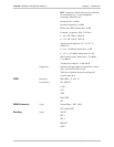
SHDSL Interface
Type
2-wire unconditioned dedicated line
Line Coding
TC-PAM
Range
See Table 1-1
Impedance
135Ω
Connector
RJ-45
Protection
ITU K.21, UL1950
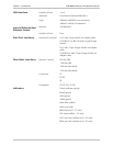
Analog Voice
Number of Voice
Channels
4 per card
Modulation Method
PCM (per ITU-T G.711 and AT&T
PUB-43801)
µ-Law or A-Law
Interfaces
E&M: 2-wire or 4-wire, supporting different
types of E&M signaling: RS-464 Types I, II,
III, and V, and BT SSDC5, configured by
software
FXS: Loop start, WINK start (reverse polarity)
for direct connection to a 2-wire telephone